THS4531
www.ti.com
SLOS358B –SEPTEMBER 2011–REVISED MARCH 2012
APPLICATION INFORMATION
TYPICAL CHARACTERISTICS TEST CIRCUITS
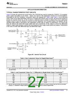
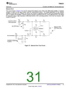
Figure 68 shows the general test circuit built on the EVM that was used for testing the THS4531. For simplicity,
power supply decoupling is not shown – please see layout in the applications section for recommendations.
Depending on the test conditions, component values are changed per Table 2 and Table 3, or as otherwise
noted. Some of the signal generators used are ac coupled 50Ω sources and a 0.22µF cap and 49.9Ω resistor to
ground are inserted across RIT on the un-driven or alternate input as shown to balance the circuit. Split-power
supply is used to ease the interface to common lab test equipment, but if properly biased, the amplifier can be
operated single-supply as described in the applications section with no impact on performance. For most of the
tests, the devices are tested with single ended input and a transformer on the output to convert the differential
output to single ended because common lab test equipment have single ended inputs and outputs. Performance
is the same or better with differential input and differential output.
VIN+
RG
RF
RO
Input From 50-Ω
Test Equipment
PD
RIT
VS+
VOUT–
THS4531
VOUT+
1:1
Output to 50-Ω
Test Equipment
+
VOCM
–
0.22 μF
ROT
0.22 μF
RG
VS–
VIN–
RO
No Connection
RF
RIT
0.22 μF
49.9 Ω
Installed to Balance
Amplifier
Figure 68. General Test Circuit
Table 2. Gain Component Values for Single-Ended Input(1)
GAIN
1 V/V
2 V/V
5 V/V
10 V/V
RF
RG
2kΩ
RIT
2kΩ
2kΩ
2kΩ
2kΩ
51.1Ω
52.3Ω
53.6Ω
57.6Ω
1kΩ
392Ω
187kΩ
(1) Note components are chosen to achieve gain and 50Ω input termination. Resistor values shown are closest standard values so gains
are approximate.
Table 3. Load Component Values For 1:1 Differential to Single-Ended Output Transformer(1)
RL
RO
ROT
ATTEN
6
100Ω
200Ω
499Ω
1kΩ
25Ω
open
86.6Ω
237Ω
487Ω
976Ω
69.8Ω
56.2Ω
52.3Ω
51.1Ω
16.8
25.5
31.8
37.9
2kΩ
(1) Note the total load includes 50Ω termination by the test equipment. Components are chosen to achieve load and 50Ω line termination
through a 1:1 transformer. Resistor values shown are closest standard values so loads are approximate.
Copyright © 2011–2012, Texas Instruments Incorporated
Submit Documentation Feedback
27
Product Folder Link(s): THS4531

 TI [ TEXAS INSTRUMENTS ]