THS4531
www.ti.com
SLOS358B –SEPTEMBER 2011–REVISED MARCH 2012
200
100
10
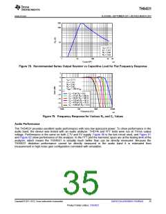
VS = 2.7 V
G = 1 V/V
RF = 2 kΩ
RL = 2 kΩ
1
1
10
100
CLOAD (pF)
1k 2k
G068
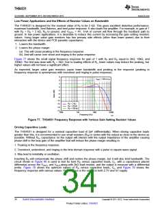
Figure 78. Recommended Series Output Resistor vs Capacitive Load for Flat Frequency Response
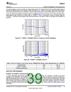
3
0
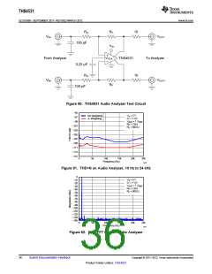
VS = 2.7 V
G = 1 V/V
−3
RF = 2 kΩ
RL = 2 kΩ
−6
VOUT = 100 mVpp
−9
CL = 0 pF,RO = 0 Ω
−12
CL = 15 pF,RO = 200 Ω
CL = 39 pF,RO = 100 Ω
CL = 120 pF,RO = 50 Ω
−15
CL = 470 pF,RO = 20 Ω
CL = 1200 pF,RO = 12 Ω
−18
−21
100k
1M
10M
100M
Frequency (Hz)
G069
Figure 79. Frequency Response for Various RO and CL Values
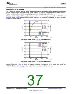
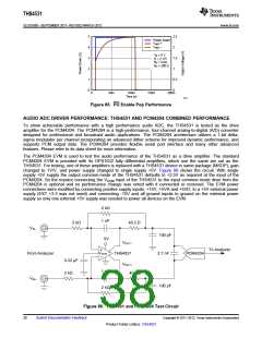
Audio Performance
The THS4531 provides excellent audio performance with very low quiescent power. To show performance in the
audio band, the device was tested with an audio analyzer. THD+N and FFT tests were run at 1Vrms output
voltage. Performance is the same on both 2.7V and 5V supply. Figure 80 is the test circuit used, and Figure 81
and Figure 82 show performance of the analyzer. In the FFT plot the harmonic spurs are at the testing limit of the
analyzer, which means the THS4531 is actually much better than can be directly measured. Because the
THS4531 distortion performance cannot be directly measured in the audio band it is estimated from
measurement in high noise gain configuration correlated with simulation.
Copyright © 2011–2012, Texas Instruments Incorporated
Submit Documentation Feedback
35
Product Folder Link(s): THS4531

 TI [ TEXAS INSTRUMENTS ]