THS4531
SLOS358B –SEPTEMBER 2011–REVISED MARCH 2012
www.ti.com
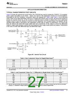
Due to the voltage divider on the output formed by the load component values, the amplifier’s output is
attenuated. The column “Atten” in Table 3 shows the attenuation expected from the resistor divider. When using
a transformer at the output as shown in Figure 68, the signal will see slightly more loss due to transformer and
line loss, and these numbers will be approximate. The standard output load used for most tests is 2kΩ with
associated 37.9dB of loss.
Frequency Response, and Output Impedance
The circuit shown in Figure 68 is used to measure the frequency response of the amplifier.
A network analyzer is used as the signal source and the measurement device. The output impedance of the
network analyzer is 50Ω and is DC coupled. RIT and RG are chosen to impedance match to 50Ω and maintain
the proper gain. To balance the amplifier, a 49.9Ω resistor to ground is inserted across RIT on the alternate input.
The output is routed to the input of the network analyzer via 50Ω coax. For 2k load, 37.9dB is added to the
measurement to refer back to the amplifier’s output per Table 3.
For output impedance, the signal is injected at VOUT with VIN left open. The voltage drop across the 2x RO
resistors is measured with a high impedance differential probe and used to calculate the impedance seen looking
into the amplifier’s output.
Distortion
At 1MHz and above, the circuit shown in Figure 68 is used to measure harmonic, intermodulation distortion, and
output impedance of the amplifier.
A signal generator is used as the signal source and the output is measured with a spectrum analyzer. The output
impedance of the signal generator is 50Ω and is AC coupled. RIT and RG are chosen to impedance match to 50Ω
and maintain the proper gain. To balance the amplifier, a 0.22µF cap and 49.9Ω resistor to ground is inserted
across RIT on the alternate input. A low-pass filter is inserted in series with the input to reduce harmonics
generated at the signal source. The level of the fundamental is measured and then a high-pass filter is inserted
at the output to reduce the fundamental so it does not generate distortion in the input of the spectrum analyzer.
Distortion in the audio band is measured using an audio analyzer. Refer to audio measurement section for detail.
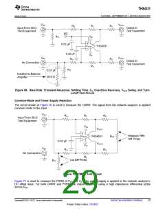
Slew Rate, Transient Response, Settling Time, Overdrive, Output Voltage, and Turn-On/Off Time
The circuit shown in Figure 69 is used to measure slew rate, transient response, settling time, overdrive
recovery, and output voltage swing. Turn on and turn off times are measured with 50Ω input termination on the
PD input, by replacing the 0.22µF capacitor with 49.9Ω resistor.
28
Submit Documentation Feedback
Copyright © 2011–2012, Texas Instruments Incorporated
Product Folder Link(s): THS4531

 TI [ TEXAS INSTRUMENTS ]