TCA6424A
SCPS193B –JULY 2010–REVISED SEPTEMBER 2010
www.ti.com
APPLICATION INFORMATION
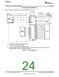
Figure 14 shows an application in which the TCA6424A can be used.
V
V
CCI
CCP
10 kW (´ 7)
V
CCI
(1.8 V)
ALARM
(see Note D)
31
27
Subsystem 1
(e.g., Alarm)
10 kW
10 kW 10 kW 10 kW
V
CC
V
V
CCI
CCP
1
2
29
30
P00
SCL
SCL
SDA
A
Master
Controller
SDA
INT
32
29
P01
INT
ENABLE
GND
RESET
RESET
B
3
P02
P03
P04
P05
P06
P07
P10
P11
P12
P13
P14
P15
P16
P17
4
5
TCA6424A
6
24
23
22
21
20
19
18
17
P27
P26
P25
P24
P23
P22
P21
P20
7
8
9
Status
Monitor
Keypad
10
11
12
13
14
15
16
26
ADDR
GND
25
A. Device address configured as 0100000 for this example.
B. P00 and P02–P10 are configured as inputs.
C. P01, P11–P17, and P20–P27 are configured as outputs.
D. Resistors are required for inputs (on P port) that may float. If a driver to an input will not let the input float, a resistor is
not needed. Outputs (in the P port) do not need pullup resistors.
Figure 14. Typical Application
24
Submit Documentation Feedback
Copyright © 2010, Texas Instruments Incorporated
Product Folder Link(s): TCA6424A

 TI [ TEXAS INSTRUMENTS ]