TCA6424A
SCPS193B –JULY 2010–REVISED SEPTEMBER 2010
www.ti.com
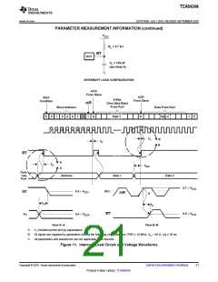
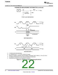
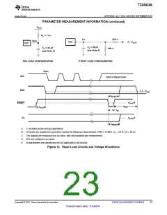
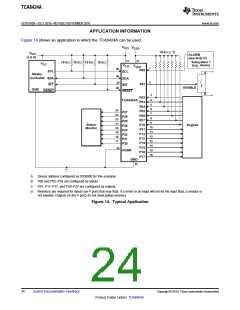
PARAMETER MEASUREMENT INFORMATION
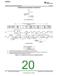
V
CCI
R
= 1 kW
L
SDA
DUT
C
= 50 pF
L
(see Note A)
SDA LOAD CONFIGURATION
Two Bytes for READ Input Port Register
(see Figure 9)
Stop
Condition Condition
(P) (S)
Start
Address
Bit 7
(MSB)
Data
Bit 7
(MSB)
Data
Bit 0
(LSB)
Stop
Condition
(P)
R/W
Bit 0
(LSB)
ACK
(A)
Address
Bit 1
t
t
sch
scl
0.7 ´ V
CCI
CCI
SCL
SDA
0.3 ´ V
t
t
icr
vd
t
t
sts
sp
t
t
icf
t
buf
vd
t
t
sps
ocf
0.7 ´ V
0.3 ´ V
CCI
CCI
t
t
vd(ack)
icr
t
sdh
t
t
icf
sds
t
sth
Repeat Start
Condition
Stop
Condition
VOLTAGE WAVEFORMS
BYTE
DESCRIPTION
2
I C address
1
2
Input register port data
A. CL includes probe and jig capacitance. tocf is measured with CL of 10 pF or 400 pF.
B. All inputs are supplied by generators having the following characteristics: PRR ≤ 10 MHz, ZO = 50 Ω, tr/tf ≤ 30 ns.
C. All parameters and waveforms are not applicable to all devices.
Figure 10. I2C Interface Load Circuit and Voltage Waveforms
20
Submit Documentation Feedback
Copyright © 2010, Texas Instruments Incorporated
Product Folder Link(s): TCA6424A

 TI [ TEXAS INSTRUMENTS ]