TCA6424A
www.ti.com
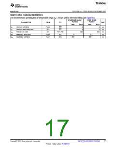
SCPS193B –JULY 2010–REVISED SEPTEMBER 2010
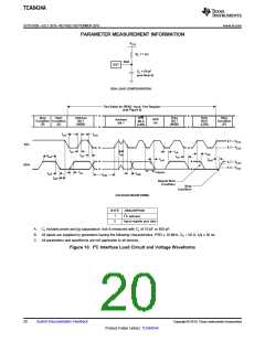
PARAMETER MEASUREMENT INFORMATION (continued)
V
CCI
R
= 4.7 kW
L
INT
DUT
C
= 100 pF
L
(see Note A)
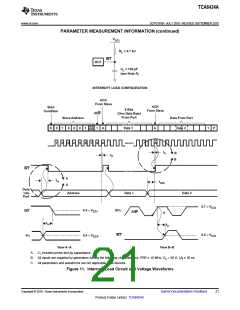
INTERRUPT LOAD CONFIGURATION
ACK
From Slave
ACK
Start
8 Bits
From Slave
Condition
R/W
1
(One Data Byte)
From Port
Slave Address
Data From Port
Data 2
AD
DR
Data 1
A
A
1
P
S
0
1
1
2
0
3
0
4
0
5
1
6
A
A
7
8
t
B
B
ir
t
ir
INT
A
t
iv
t
sps
A
Data
Into
Port
Address
Data 1
Data 2
0.7 ´ V
CCI
0.5 ´ V
SCL
INT
CCI
R/W
A
t
iv
t
ir
0.5 ´ V
INT
0.5 ´ V
Pn
CCI
CCP
View A−A
A. CL includes probe and jig capacitance.
View B−B
B. All inputs are supplied by generators having the following characteristics: PRR ≤ 10 MHz, ZO = 50 Ω, tr/tf ≤ 30 ns.
C. All parameters and waveforms are not applicable to all devices.
Figure 11. Interrupt Load Circuit and Voltage Waveforms
Copyright © 2010, Texas Instruments Incorporated
Submit Documentation Feedback
21
Product Folder Link(s): TCA6424A

 TI [ TEXAS INSTRUMENTS ]