TCA6424A
www.ti.com
SCPS193B –JULY 2010–REVISED SEPTEMBER 2010
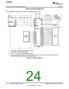
Minimizing ICC When I/Os Control LEDs
When the I/Os are used to control LEDs, normally they are connected to VCC through a resistor as shown in
Figure 14. The LED acts as a diode so, when the LED is off, the I/O VIN is about 1.2 V less than VCC. The ΔICC
parameter in Electrical Characteristics shows how ICC increases as VIN becomes lower than VCC. Designs that
must minimize current consumption, such as battery power applications, should consider maintaining the I/O pins
greater than or equal to VCC when the LED is off.
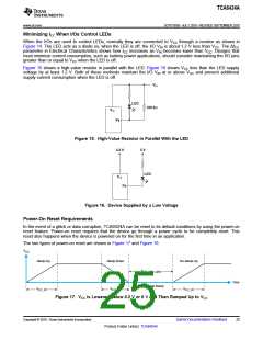
Figure 15 shows a high-value resistor in parallel with the LED. Figure 16 shows VCC less than the LED supply
voltage by at least 1.2 V. Both of these methods maintain the I/O VIN at or above VCC and prevent additional
supply current consumption when the LED is off.
VCC
LED
100 kW
VCC
Px
Figure 15. High-Value Resistor in Parallel With the LED
3.3 V
5 V
LED
VCC
Px
Figure 16. Device Supplied by a Low Voltage
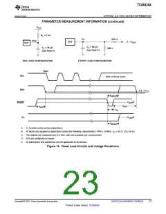
Power-On Reset Requirements
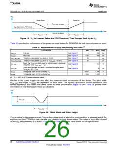
In the event of a glitch or data corruption, TCA6424A can be reset to its default conditions by using the power-on
reset feature. Power-on reset requires that the device go through a power cycle to be completely reset. This
reset also happens when the device is powered on for the first time in an application.
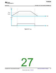
The two types of power-on reset are shown in Figure 17 and Figure 18.
V
CC
Ramp-Up
Ramp-Down
Re-Ramp-Up
V
CC_TRR_GND
Time
Time to Re-Ramp
V
V
V
CC_RT
CC_FT
CC_RT
Figure 17. VCC is Lowered Below 0.2 V or 0 V and Then Ramped Up to VCC
Copyright © 2010, Texas Instruments Incorporated
Submit Documentation Feedback
25
Product Folder Link(s): TCA6424A

 TI [ TEXAS INSTRUMENTS ]