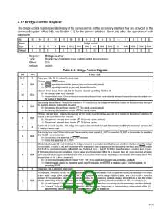
Table 4–6. Bridge Control Register (Continued0)
BIT
TYPE
FUNCTION
ISA enable. When bit 2 is set, the bridge blocks the forwarding of ISA I/O transactions from the primary to the secondary,
addressingthelast768bytesineach1K-byteblock. Thisappliesonlytotheaddresses(definedbytheI/Owindowregisters)
that are located in the first 64K bytes of PCI I/O address space. From the secondary to the primary, I/O transactions are
forwardediftheyaddressthelast768bytesineach1K-byteblockintheaddressrangespecifiedintheI/Owindowregisters.
Bit 2 is encoded as:
2
R/W
0 = Forward all I/O addresses in the address range defined by the I/O base and I/O limit registers (default).
1 = Block forwarding of ISA I/O addresses in the address range defined by the I/O base and I/O limit registers when
these I/O addresses are in the first 64K bytes of PCI I/O address space and address the top 768 bytes of each
1K-byte block.
SERR enable. Bit 1 controls the forwarding of secondary interface SERR assertions to the primary interface. Only when
this bit is set will the bridge forward S_SERR to the primary bus signal P_SERR. For the primary interface to assert SERR,
bit 8 of the command register (offset 04h, see Section 4.3) must be set.
0 = SERR disabled (default)
1
0
R/W
R/W
1 = SERR enabled
Parity error response enable. Bit 0 controls the bridge response to parity errors on the secondary interface. When this bit
is set, the bridge asserts S_PERR to report parity errors on the secondary interface.
0 = Ignore address and parity errors on the secondary interface (default).
1 = Enable parity error reporting and detection on the secondary interface.
4–16

 TI [ TEXAS INSTRUMENTS ]