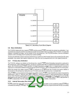
bus grant terminals. Including the bridge, there are a total of five potential secondary bus masters. These request
and grant signals are connected to the internal arbiter. When an external arbiter is implemented, S_REQ3–S_REQ0
and S_GNT3–S_GNT0 are placed in a high impedance mode.
3.6.3 External Secondary Bus Arbitration
An external secondary bus arbiter can be used instead of the PCI2250 internal arbiter. When using an external arbiter,
the PCI2250’s internal arbiter should be disabled by pulling S_CFN high.
When an external secondary bus arbiter is used, the PCI2250 internally reconfigures the S_REQ0 and S_GNT0
signals so that S_REQ0 becomes the secondary bus grant for the bridge and S_GNT0 becomes the secondary bus
request for the bridge. This is done because S_REQ0 is an input and can thus be used to provide the grant input to
the bridge, and S_GNT0 is an output and can thus provide the request output from the bridge.
When an external arbiter is used, all unused secondary bus grant outputs (S_GNT3–S_GNT1) are placed in a high
impedance mode. Any unused secondary bus request inputs (S_REQ3–S_REQ1) should be pulled high to prevent
the inputs from oscillating.
3.7 Decode Options
The PCI2250 supports positive, subtractive, and negative decoding but defaults to positive decoding on the primary
interface and negative decoding on the secondary bus. Positive decoding is a method of address decoding in which
a device responds only to accesses within an assigned address range. Negative decoding is a method of address
decoding in which a device responds only to accesses outside an assigned address range. Subtractive decoding is
a method of address decoding in which a device responds to accesses not claimed by any other devices on the bus.
Subtractive decoding can be enabled on the primary bus or the secondary bus.
3.8 Extension Windows With Programmable Decoding
The PCI2250 provides two programmable 32-bit extension windows. Each window can be programmed to be a
prefetchable memory window, a nonprefetchable memory window, or an I/O window. The TI extension memory
windows have a 4K-byte granularity, and the I/O windows have a doubleword granularity. These extension windows
can be positively decoded on either the primary bus or secondary bus.
The standard PCI-to-PCI bridge memory and I/O windows specified by the PCI-to-PCI Bridge Specification have a
1M-byte and 4K-byte granularity, respectively (see Section 4.20, Memory Base Register and Section 4.26, I/O Base
Upper 16 Bits Register). The TI extension windows provide smaller granularity for memory and I/O windows. The
extension windows’ granularity matches the requirements of CardBus card windows, which also have 4K-byte
granularity for memory windows and doubleword granularity for I/O windows. When a CardBus I/O card is sitting
behind the bridge, the smaller doubleword I/O window granularity with the extension windows allows a smaller I/O
window than the 4K-byte window with the standard I/O base and limit registers.
A common I/O base address for popular sound cards is 300h–303h. Using the TI extension windows and configuring
the base I/O address for 300h establishes a 4-byte I/O address window from 300h–303h for communicating with the
sound card. Using the bridge’s standard I/O base register requires a minimum 4K-byte window of memory.
The extension windows can be excluded from the primary bus decoding, thus creating a hole in a primary window
address range.
3.9 System Error Handling
The PCI2250 can be configured to signal a system error (SERR) under a variety of conditions. The P_SERR event
disable register (offset 64h, see Section 5.18) and the P_SERR status register (offset 6Ah, see Section 5.20) provide
control and status bits for each condition for which the bridge can signal SERR. These individual bits enable SERR
reporting for both downstream and upstream transactions.
By default, the PCI2250 will not signal SERR. If the PCI2250 is configured to signal SERR by setting bit 8 of the
command register (offset 04h, see Section 4.3), then the bridge signals SERR if any of the error conditions in the
3–6

 TI [ TEXAS INSTRUMENTS ]