OMAP-L137 Low-Power Applications Processor
SPRS563A–SEPTEMBER 2008–REVISED OCTOBER 2008
www.ti.com
6.3 Power Supplies
6.3.1 Power-on Sequence
OMAP-L13x devices include on chip logic that ensures I/O pins are tri-stated during the power on ramp,
as long as the RESET\ pin is asserted. This is true even if the core voltage (CVDD) has not yet ramped.
Normally, the only requirement during the power on ramp is that both the RESET\ and TRST\ pins remain
asserted (low) until after the power supply rails have fully ramped.
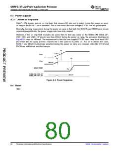
However, if the on chip USB modules are used; then to limit any noise on the USB0_DM, USB0_DP,
USB1_DM, and USB1_DP pins to less than 200mV during the power on ramp, the sequence illustrated in
Figure 6-4 must be followed. The requirement is that the core supply (CVDD) must ramp to at least 0.9V
(1) before the IO supply (DVDD) reaches the 1.65V point in its ramp (2). And as is always the case,
RESET\ and TRST\ must remain asserted during the power on ramp and released only after CVDD and
DVDD are within their specified ranges.
(2)
1.65 V
DVDD
(3)
(1)
CVDD
900 mV
RESET, TRST
VIL
USB0_DM, USB0_DP
USB1_DM, USB1_DP
200 mV
Figure 6-4. Power Sequence
6.4 Reset
TBD
80
Peripheral Information and Electrical Specifications
Submit Documentation Feedback

 TI [ TEXAS INSTRUMENTS ]