ꢀꢁ ꢂꢃ ꢄꢅ
ꢆ ꢇꢈ ꢁ ꢉꢊ ꢋꢌ ꢍꢉ ꢎ ꢏꢎꢉ ꢈ ꢁꢐ ꢑ ꢒ ꢐꢀꢁꢎꢓ ꢋ ꢉꢐ ꢔ ꢒꢋꢑꢁ ꢋ ꢑꢆ
ꢇꢈ ꢁ ꢊ ꢑ ꢋꢓꢕ ꢀ ꢎꢁꢐ ꢑꢆ
SLVS033F − FEBRUARY 1990 − REVISED NOVEMBER 2004
PRINCIPLES OF OPERATION
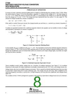
A review of a basic switched-capacitor building block is helpful in understanding the operation of the LT1054. When
the switch shown in Figure 12 is in the left position, capacitor C1 charges to the voltage at V1. The total charge on
C1 is q1 = C1V1. When the switch is moved to the right, C1 is discharged to the voltage at V2. After this discharge
time, the charge on C1 is q2 = C1V2. The charge has been transferred from the source V1 to the output V2. The
amount of charge transferred is shown in equation 1.
Dq + q1 * q2 + C1(V1 * V2)
If the switch is cycled f times per second, the charge transfer per unit time (i.e., current) is as shown in equation 2.
I + f Dq + f C1(1 * V2)
(1)
(2)
To obtain an equivalent resistance for a switched-capacitor network, this equation can be rewritten in terms of voltage
and impedance equivalence as shown in equation 3.
V1 * V2
1ńfC1
V1 * V2
REQUIV
I +
+
ǒ
Ǔ
(3)
V1
V2
L
f
R
C1
C2
Figure 12. Switched-Capacitor Building Block
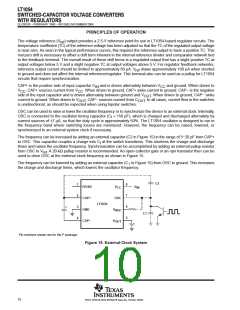
A new variable, R
, is defined as R
= 1 ÷ fC1. The equivalent circuit for the switched-capacitor network is
EQUIV
EQUIV
shown in Figure 13. The LT1054 has the same switching action as the basic switched-capacitor building block. Even
though this simplification does not include finite switch-on resistance and output-voltage ripple, it provides an insight
into how the device operates.
R
EQUIV
V1
V2
C2
R
L
1
fC1
REQUIV
+
Figure 13. Switched-Capacitor Equivalent Circuit
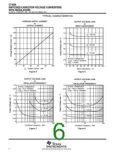
These simplified circuits explain voltage loss as a function of oscillator frequency (see Figure 7). As oscillator
frequency is decreased, the output impedance eventually is dominated by the 1/fC1 term, and voltage losses rise.
Voltage losses also rise as oscillator frequency increases. This is caused by internal switching losses that occur due
to some finite charge being lost on each switching cycle. This charge loss per-unit-cycle, when multiplied by the
switching frequency, becomes a current loss. At high frequency, this loss becomes significant and voltage losses
again rise.
The oscillator of the LT1054 is designed to operate in the frequency band where voltage losses are at a minimum.
8
POST OFFICE BOX 655303 • DALLAS, TEXAS 75265

 TI [ TEXAS INSTRUMENTS ]