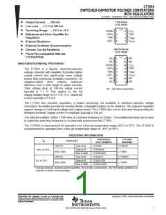
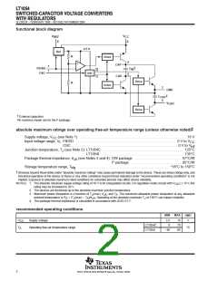
ꢀꢁ ꢂꢃ ꢄꢅ
ꢆ ꢇꢈ ꢁ ꢉꢊ ꢋꢌ ꢍꢉ ꢎ ꢏꢎꢉ ꢈ ꢁꢐ ꢑ ꢒ ꢐꢀꢁꢎꢓ ꢋ ꢉꢐ ꢔ ꢒꢋꢑꢁ ꢋ ꢑꢆ
ꢇꢈ ꢁ ꢊ ꢑ ꢋꢓꢕ ꢀ ꢎꢁꢐ ꢑꢆ
SLVS033F − FEBRUARY 1990 − REVISED NOVEMBER 2004
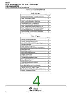
TYPICAL CHARACTERISTICS
Table of Graphs
FIGURE
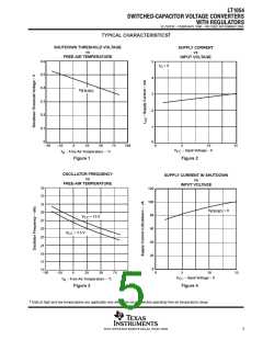
Shutdown threshold voltage vs Free-air temperature
Supply current vs Input voltage
1
2
Oscillator frequency vs Free-air temperature
Supply current in shutdown vs Input voltage
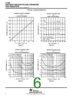
Average supply current vs Output current
Output voltage loss vs Input capacitance
Output voltage loss vs Oscillator frequency (10 µF)
Output voltage loss vs Oscillator frequency (100 µF)
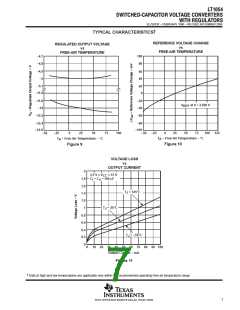
Regulated output voltage vs Free-air temperature
Reference voltage change vs Free-air temperature
Voltage loss vs Output current
3
4
5
6
7
8
9
10
11
Table of Figures
FIGURE
12
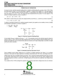
Switched-Capacitor Building Block
Switched-Capacitor Equivalent Circuit
13
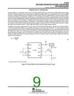
Circuit With Load Connected From V
External-Clock System
to V
OUT
14
CC
15
Basic Regulation Configuration
16
Power-Dissipation-Limiting Resistor in Series With C
Motor-Speed Servo
17
IN
18
Basic Voltage Inverter
19
Basic Voltage Inverter/Regulator
Negative-Voltage Doubler
20
21
Positive-Voltage Doubler
22
100-mA Regulating Negative Doubler
Dual-Output Voltage Doubler
5-V to 12-V Converter
23
24
25
Strain-Gage Bridge Signal Conditioner
3.5-V to 5-V Regulator
26
27
Regulating 200-mA +12-V to −5-V Converter
Digitally Programmable Negative Supply
28
29
Positive Doubler With Regulation (5-V to 8-V Converter)
Negative Doubler With Regulator
30
31
4
POST OFFICE BOX 655303 • DALLAS, TEXAS 75265

 TI [ TEXAS INSTRUMENTS ]