ꢀꢁ ꢂꢃ ꢄꢅ
ꢆ ꢇꢈ ꢁ ꢉꢊ ꢋꢌ ꢍꢉ ꢎ ꢏꢎꢉ ꢈ ꢁꢐ ꢑ ꢒ ꢐꢀꢁꢎꢓ ꢋ ꢉꢐ ꢔ ꢒꢋꢑꢁ ꢋ ꢑꢆ
ꢇꢈ ꢁ ꢊ ꢑ ꢋꢓꢕ ꢀ ꢎꢁꢐ ꢑꢆ
SLVS033F − FEBRUARY 1990 − REVISED NOVEMBER 2004
PRINCIPLES OF OPERATION
The voltage reference (V ) output provides a 2.5-V reference point for use in LT1054-based regulator circuits. The
ref
temperature coefficient (TC) of the reference voltage has been adjusted so that the TC of the regulated output voltage
is near zero. As seen in the typical performance curves, this requires the reference output to have a positive TC. This
nonzero drift is necessary to offset a drift term inherent in the internal reference divider and comparator network tied
to the feedback terminal. The overall result of these drift terms is a regulated output that has a slight positive TC at
output voltages below 5 V and a slight negative TC at output voltages above 5 V. For regulator feedback networks,
reference output current should be limited to approximately 60 µA. V draws approximately 100 µA when shorted
ref
to ground and does not affect the internal reference/regulator. This terminal also can be used as a pullup for LT1054
circuits that require synchronization.
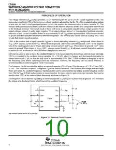
CAP+ is the positive side of input capacitor C and is driven alternately between V
and ground. When driven to
IN
CC
V
, CAP+ sources current from V . When driven to ground, CAP+ sinks current to ground. CAP− is the negative
CC
CC
side of the input capacitor and is driven alternately between ground and V
current to ground. When driven to V
. When driven to ground, CAP− sinks
OUT
OUT
, CAP− sources current from C
. In all cases, current flow in the switches
OUT
is unidirectional, as should be expected when using bipolar switches.
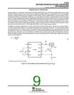
OSC can be used to raise or lower the oscillator frequency or to synchronize the device to an external clock. Internally,
OSC is connected to the oscillator timing capacitor (C ≈ 150 pF), which is charged and discharged alternately by
t
current sources of 7 µA, so that the duty cycle is approximately 50%. The LT1054 oscillator is designed to run in
the frequency band where switching losses are minimized. However, the frequency can be raised, lowered, or
synchronized to an external system clock if necessary.
The frequency can be increased by adding an external capacitor (C2 in Figure 15) in the range of 5−20 pF from CAP+
to OSC. This capacitor couples a charge into C at the switch transitions. This shortens the charge and discharge
t
times and raises the oscillator frequency. Synchronization can be accomplished by adding an external pullup resistor
from OSC to V . A 20-kΩ pullup resistor is recommended. An open-collector gate or an npn transistor then can be
ref
used to drive OSC at the external clock frequency as shown in Figure 15.
The frequency can be lowered by adding an external capacitor (C in Figure 15) from OSC to ground. This increases
1
the charge and discharge times, which lowers the oscillator frequency.
C2
1
2
3
4
8
7
6
5
FB/SD
CAP+
GND
V
V
IN
CC
OSC
LT1054
+
V
REF
C1
CAP−
V
OUT
Pin numbers shown are for the P package.
Figure 15. External-Clock System
10
POST OFFICE BOX 655303 • DALLAS, TEXAS 75265

 TI [ TEXAS INSTRUMENTS ]