LM5116
SNVS499G –FEBRUARY 2007–REVISED MARCH 2013
www.ti.com
board is recommended as a means to connect the quiet end (input voltage ground side) of the input filter
capacitors to the output filter capacitors and the PGND pin of the regulator. Connect all of the low power ground
connections (CSS, RT, CRAMP) directly to the regulator AGND pin. Connect the AGND and PGND pins together
through to a topside copper area covering the entire underside of the device. Place several vias in this underside
copper area to the ground plane.
The highest power dissipating components are the two power MOSFETs. The easiest way to determine the
power dissipated in the MOSFETs is to measure the total conversion losses (PIN - POUT), then subtract the power
losses in the output inductor and any snubber resistors. The resulting power losses are primarily in the switching
MOSFETs.
If a snubber is used, the power loss can be estimated with an oscilloscope by observation of the resistor voltage
drop at both turn-on and turn-off transitions. Assuming that the RC time constant is << 1 / fSW
.
P = C x V2 x fSW
(33)
The regulator has an exposed thermal pad to aid power dissipation. Selecting MOSFETs with exposed pads will
aid the power dissipation of these devices. Careful attention to RDS(ON) at high temperature should be observed.
Also, at 250 kHz, a MOSFET with low gate capacitance will result in lower switching losses.
Comprehensive Equations
CURRENT SENSE RESISTOR AND RAMP CAPACITOR
T = 1 / fSW, gm = 5 µA/V, A = 10 V/V. IOUT is the maximum output current at current limit.
General Method for VOUT < 5V:
VCS(TH)
RS
=
5 - VOUT
VIN(MIN)
1 +
1 +
VOUT x T
2 x L
VOUT
VOUT x T
L
IOUT
-
x 1 -
x
+
VIN(MIN)
5 - VOUT
VIN(MAX)
(34)
(35)
5 - VOUT
VIN(MAX)
gm x L
A x RS
x
1 +
CRAMP
=
General Method for 5V < VOUT < 7.5V:
VCS(TH)
RS
=
VOUT x T
2 x L
VOUT
VOUT x T
L
IOUT
-
1 -
x
+
VIN(MIN)
(36)
(37)
gm x L
A x RS
5 - VOUT
VIN(MIN)
x
1 +
CRAMP
=
Best Performance Method:
This minimizes the current limit deviation due to changes in line voltage, while maintaining near optimal slope
compensation.
Calculate optimal slope current, IOS = (VOUT / 3) x 10 µA/V. For example, at VOUT = 7.5V, IOS = 25 µA.
VCS(TH)
IOS x L
RS
=
CRAMP =
VOUT x A x RS
VOUT x T
IOUT
+
L
(38)
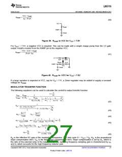
Calculate VRAMP at the nominal input voltage.
VOUT ((VIN œ VOUT) x gm + IOS) x T
x
VRAMP
=
VIN
CRAMP
(39)
For VOUT > 7.5V, install a resistor from the RAMP pin to VCC.
26
Submit Documentation Feedback
Copyright © 2007–2013, Texas Instruments Incorporated
Product Folder Links: LM5116

 TI [ TEXAS INSTRUMENTS ]