LM359
SNOSBT4C –MAY 1999–REVISED MARCH 2013
www.ti.com
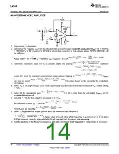
AN INVERTING VIDEO AMPLIFIER
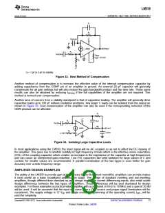
1. Basic circuit configuration:
2. Determine the required ISET from the characteristic curves for gain bandwidth product.GBWMIN= 10 × 10 MHz
= 100 MHzFor a flat response to 10 MHz a closed loop response to two octaves above 10 MHz (40 MHz) will
be sufficient.
Actual GBW = 10 × 40 MHz = 400 MHz ISET required = 0.5 mA
3. Determine maximum value for Rf to provide stable DC biasing
Optimum
output DC level for maximum symmetrical swing without clipping is:
Rf(MAX)
This value should not be exceeded for predictable
can now be found:
DC biasing.
4. Select Rs to be large enough so as not to appreciably load the input termination resistance:Rs ≥ 750Ω; Let Rs
= 750Ω
5. Select Rf for appropriate gain:
predictability is insured.
7.5 kΩ is less than the calculated Rf(MAX) so DC
6. Since Rf = 7.5k, for the output to be biased to 5.1 VDC
the reference current IIN(+) must be:
Now Rb can be found by:
,
7. Select Ci to provide the proper gain for the 8 Hz minimum input frequency:
A larger value of Ci will allow a flat frequency response down to 8 Hz and a
0.01 μF ceramic capacitor in parallel with Ci will maintain high frequency gain accuracy.
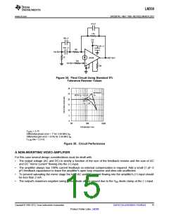
8. Test for peaking of the frequency response and add a feedback “lead” capacitor to compensate if necessary.
14
Submit Documentation Feedback
Copyright © 1999–2013, Texas Instruments Incorporated
Product Folder Links: LM359

 TI [ TEXAS INSTRUMENTS ]