LM359
www.ti.com
SNOSBT4C –MAY 1999–REVISED MARCH 2013
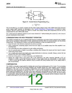
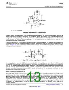
Cf = 1 pF to 5 pF for stability
Figure 32. Best Method of Compensation
Another method of compensation is to increase the effective value of the internal compensation capacitor by
adding capacitance from the COMP pin of an amplifier to ground. An external 20 pF capacitor will generally
compensate for all gain settings but will also reduce the gain bandwidth product and the slew rate. These same
results can also be obtained by reducing ISET(IN) if the full capabilities of the amplifier are not required. This
method is termed over-compensation.
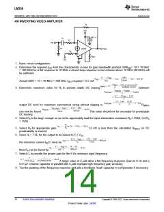
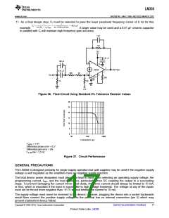
Another area of concern from a stability standpoint is that of capacitive loading. The amplifier will generally drive
capacitive loads up to 100 pF without oscillation problems. Any larger C loads can be isolated from the output as
shown in Figure 33. Over-compensation of the amplifier can also be used if the corresponding reduction of the
GBW product can be afforded.
Figure 33. Isolating Large Capacitive Loads
In most applications using the LM359, the input signal will be AC coupled so as not to affect the DC biasing of
the amplifier. This gives rise to another subtlety of high frequency circuits which is the effective series inductance
(ESL) of the coupling capacitor which creates an increase in the impedance of the capacitor at high frequencies
and can cause an unexpected gain reduction. Low ESL capacitors like solid tantalum for large values of C and
ceramic for smaller values are recommended. A parallel combination of the two types is even better for gain
accuracy over a wide frequency range.
AMPLIFIER DESIGN EXAMPLES
The ability of the LM359 to provide gain at frequencies higher than most monolithic amplifiers can provide makes
it most useful as a basic broadband amplification stage. The design of standard inverting and non-inverting
amplifiers, though different than standard op amp design due to the current differencing inputs, also entail subtle
design differences between the two types of amplifiers. These differences will be best illustrated by design
examples. For these examples a practical video amplifier with a passband of 8 Hz to 10 MHz and a gain of 20 dB
will be used. It will be assumed that the input will come from a 75Ω source and proper signal termination will be
considered. The supply voltage is 12 VDC and single resistor programming of the operating current, ISET, will be
used for simplicity.
Copyright © 1999–2013, Texas Instruments Incorporated
Submit Documentation Feedback
13
Product Folder Links: LM359

 TI [ TEXAS INSTRUMENTS ]