LM26420, LM26420-Q0, LM26420-Q1
www.ti.com
SNVS579J –FEBRUARY 2009–REVISED SEPTEMBER 2015
Typical Characteristics (continued)
All curves taken at VIN = 5 V with configuration in typical application circuits shown in Application and Implementation section
of this datasheet. TJ = 25°C, unless otherwise specified.
0.78
0.77
0.76
0.75
0.74
0.73
0.72
0.71
0.70
-50 -25
0
25
50
75 100 125
TEMPERATURE (°C)
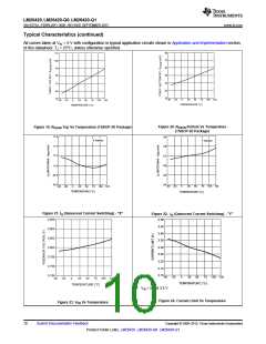
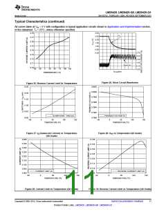
Figure 26. Short Circuit Waveforms
Figure 25. Reverse Current Limit Vs Temperature
12.50
0.8002
0.8000
0.7998
0.7996
0.7994
0.7992
0.7990
12.00
11.50
11.00
10.50
10.00
IQ SWITCHING - VIND (mA)
FEEDBACK VOLTAGE (V)
0
50
TEMPERATURE (öC)
100
150
0
50
100
150
±50
±50
TEMPERATURE (|C)
C002
C004
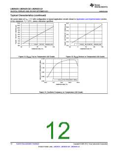
Figure 27. IQ (Quiescent Current) vs Temperature
(Q0 Grade)
Figure 28. VFB vs Temperature (Q0 Grade)
3.400
0.740
3.350
3.300
3.250
3.200
3.150
3.100
3.050
3.000
0.735
0.730
0.725
0.720
0.715
0.710
0.705
CURRENT LIMIT (A)
REVERSE CURRENT LIMIT (A)
-50
0
50
TEMPERATURE (öꢀ
100
150
-50
0
50
100
150
TEMPERATURE (|C)
C005
C006
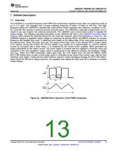
Figure 29. Current Limit vs Temperature (Q0 Grade)
Figure 30. Reverse Current Limit vs Temperature (Q0 Grade)
Copyright © 2009–2015, Texas Instruments Incorporated
Submit Documentation Feedback
11
Product Folder Links: LM26420 LM26420-Q0 LM26420-Q1

 TI [ TEXAS INSTRUMENTS ]