LM2587
SNVS115D –APRIL 2000–REVISED APRIL 2013
www.ti.com
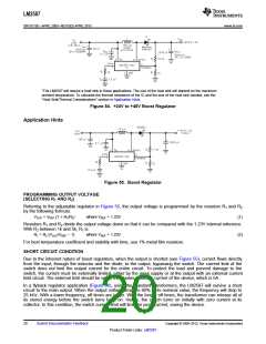
*The LM2587 will require a heat sink in these applications. The size of the heat sink will depend on the maximum
ambient temperature. To calculate the thermal resistance of the IC and the size of the heat sink needed, see the
“Heat Sink/Thermal Considerations” section in Application Hints.
Figure 54. +24V to +48V Boost Regulator
Application Hints
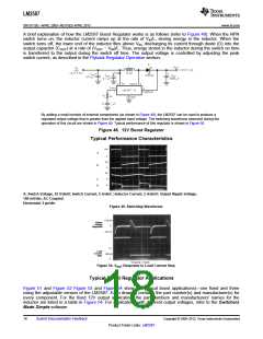
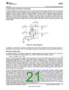
Figure 55. Boost Regulator
PROGRAMMING OUTPUT VOLTAGE
(SELECTING R1 AND R2)
Referring to the adjustable regulator in Figure 55, the output voltage is programmed by the resistors R1 and R2
by the following formula:
VOUT = VREF (1 + R1/R2)
where VREF = 1.23V
(1)
Resistors R1 and R2 divide the output voltage down so that it can be compared with the 1.23V internal reference.
With R2 between 1k and 5k, R1 is:
R1 = R2 (VOUT/VREF − 1)
where VREF = 1.23V
(2)
For best temperature coefficient and stability with time, use 1% metal film resistors.
SHORT CIRCUIT CONDITION
Due to the inherent nature of boost regulators, when the output is shorted (see Figure 55), current flows directly
from the input, through the inductor and the diode, to the output, bypassing the switch. The current limit of the
switch does not limit the output current for the entire circuit. To protect the load and prevent damage to the
switch, the current must be externally limited, either by the input supply or at the output with an external current
limit circuit. The external limit should be set to the maximum switch current of the device, which is 5A.
In a flyback regulator application (Figure 56), using the standard transformers, the LM2587 will survive a short
circuit to the main output. When the output voltage drops to 80% of its nominal value, the frequency will drop to
25 kHz. With a lower frequency, off times are larger. With the longer off times, the transformer can release all of
its stored energy before the switch turns back on. Hence, the switch turns on initially with zero current at its
collector. In this condition, the switch current limit will limit the peak current, saving the device.
20
Submit Documentation Feedback
Copyright © 2000–2013, Texas Instruments Incorporated
Product Folder Links: LM2587

 TI [ TEXAS INSTRUMENTS ]