LM2587
SNVS115D –APRIL 2000–REVISED APRIL 2013
www.ti.com
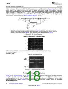
A brief explanation of how the LM2587 Boost Regulator works is as follows (refer to Figure 48). When the NPN
switch turns on, the inductor current ramps up at the rate of VIN/L, storing energy in the inductor. When the
switch turns off, the lower end of the inductor flies above VIN, discharging its current through diode (D) into the
output capacitor (COUT) at a rate of (VOUT − VIN)/L. Thus, energy stored in the inductor during the switch on time
is transferred to the output during the switch off time. The output voltage is controlled by adjusting the peak
switch current, as described in the Flyback Regulator Operation section.
By adding a small number of external components (as shown in Figure 48), the LM2587 can be used to produce a
regulated output voltage that is greater than the applied input voltage. The switching waveforms observed during the
operation of this circuit are shown in Figure 49. Typical performance of this regulator is shown in Figure 50.
Figure 48. 12V Boost Regulator
Typical Performance Characteristics
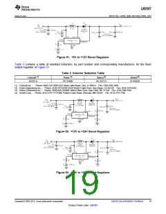
A: Switch Voltage, 10 V/divB: Switch Current, 5 A/divC: Inductor Current, 5 A/divD: Output Ripple Voltage,
100 mV/div, AC-Coupled
Horizontal: 2 μs/div
Figure 49. Switching Waveforms
Figure 50. VOUT Response to Load Current Step
Typical Boost Regulator Applications
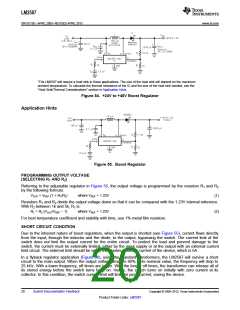
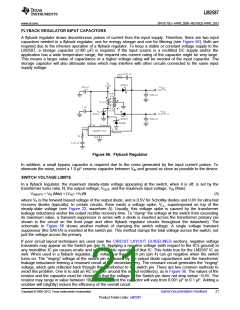
Figure 51 and Figure 52 Figure 53 and Figure 54 show four typical boost applications)—one fixed and three
using the adjustable version of the LM2587. Each drawing contains the part number(s) and manufacturer(s) for
every component. For the fixed 12V output application, the part numbers and manufacturers' names for the
inductor are listed in a table in Figure 54. For applications with different output voltages, refer to the Switchers
Made Simple software.
18
Submit Documentation Feedback
Copyright © 2000–2013, Texas Instruments Incorporated
Product Folder Links: LM2587

 TI [ TEXAS INSTRUMENTS ]