DRV593
DRV594
www.ti.com
SLOS401A - SEPTEMBER 2002 REVISED - OCTOBER 2002
LC FILTER IN THE FREQUENCY DOMAIN
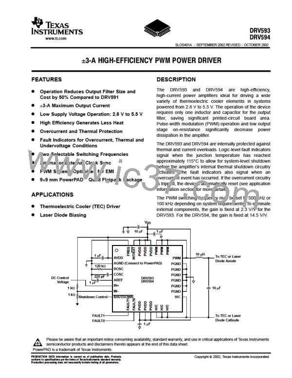
The transfer function for a second-order low-pass filter (Figures 17 and 18) is shown in equation (5):
1
(5)
H
(jw) +
LP
2
jw
w
–ǒ Ǔ
w
1
Q
)
) 1
w
0
0
1
w
+
0
Ǹ
LC
Q + quality factor
w + DRV593 or DRV594 switching frequency
For the DRV593 and DRV594, the differential output switching frequency is typically selected to be 500 kHz.
The resonant frequency for the filter is typically chosen to be at least one order of magnitude lower than the
switching frequency. equation (5) may then be simplified to give the following magnitude equation (6). These
equations assume the use of the filter in Figure 22.
(6)
f
s
ŤHLPŤdB
+ –40 log ǒ Ǔ
Ǹ
f
o
1
f
+
o
2p LC
f + 500 kHz (DRV593 or DRV594 switching frequency)
s
If L=10 µH and C=10 µF, the cutoff frequency is 15.9 kHz, which corresponds to –60 dB of attenuation at the
500 kHz switching frequency. For VDD = 5 V, the amount of ripple voltage at the TEC element is approximately
5 mV.
The average TEC element has a resistance of 1.5 Ω, so the ripple current through the TEC is approximately
3.4 mA. At the 3-A maximum output current of the DRV593 and DRV594, this 5.4 mA corresponds to 0.11%
ripple current, causing less than 0.0001% reduction of the maximum temperature differential of the TEC
element (see equation 4).
LC FILTER IN THE TIME DOMAIN
The ripple current of an inductor may be calculated using equation (7):
(7)
ǒV –V ǓDT
s
O
TEC
L
DI
+
L
D + duty cycle (0.5 worst case)
T + 1ńf + 1ń500 kHz
s
s
For V = 5 V, V
= 2.5 V, and L = 10 µH, the inductor ripple current is 250 mA. To calculate how much of that
O
TEC
ripple current flows through the TEC element, however, the properties of the filter capacitor must be considered.
For relatively small capacitors (less than 22 µF) with very low equivalent series resistance (ESR, less than
10 mΩ), such as ceramic capacitors, the following equation (8) may be used to estimate the ripple voltage on
the capacitor due to the change in charge:
2
(8)
f
2
o
p
ǒ
Ǔ
1–D ǒ Ǔ VTEC
DV
+
C
2
f
s
D + duty cycle
f + 500 kHz
s
1
f
+
o
Ǹ
2p LC
15

 TI [ TEXAS INSTRUMENTS ]