DRV593
DRV594
www.ti.com
SLOS401A - SEPTEMBER 2002 REVISED - OCTOBER 2002
FIXED INTERNAL GAIN
The differential output voltage may be calculated using equation (10):
(10)
vǒV
IN–Ǔ
V
+ V
–V
OUT) OUT–
+ A
–V
IN)
O
A is the voltage gain, which is fixed internally at 2.3 V/V for DRV593 and 14.5 V/V for DRV594. The maximum
V
and minimum ratings are provided in the electrical specification table at the beginning of the data sheet.
POWER SUPPLY DECOUPLING
To reduce the effects of high-frequency transients or spikes, a small ceramic capacitor, typically 0.1 µF to 1 µF,
should be placed as close to each set of PVDD pins of the DRV593 and DRV594 as possible. For bulk
decoupling, a 10 µF to 100 µF tantalum or aluminum electrolytic capacitor should be placed relatively close to
the DRV593 and DRV594.
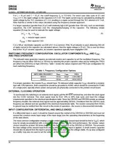
AREF CAPACITOR
The AREF terminal is the output of an internal mid-rail voltage regulator used for the onboard oscillator and ramp
generator. The regulator may not be used to provide power to any additional circuitry. A 1 µF ceramic capacitor
must be connected from AREF to AGND for stability (see oscillator components above for AGND connection
information).
SHUTDOWN OPERATION
The DRV593 and DRV594 include a shutdown mode that disables the outputs and places the device in a low
supply current state. The SHUTDOWN pin may be controlled with a TTL logic signal. When SHUTDOWN is
held high, the device operates normally. When SHUTDOWN is held low, the device is placed in shutdown. The
SHUTDOWN pin must not be left floating. If the shutdown feature is unused, the pin may be connected to VDD.
FAULT REPORTING
The DRV593 and DRV594 include circuitry to sense three faults:
D
D
D
Overcurrent
Undervoltage
Overtemperature
These three fault conditions are decoded via the FAULT1 and FAULT0 terminals. Internally, these are
open-drain outputs, so an external pullup resistor of 5 kΩ or greater is required.
Table 2. Fault Indicators
FAULT1
FAULT0
0
1
0
1
0
0
1
1
Overcurrent
Undervoltage
Overtemperature
Normal operation
The overcurrent fault is reported when the output current exceeds four amps. As soon as the condition is
sensed, the overcurrent fault is set and the outputs go into a high-impedance state for approximately 3 µs to
5 µs (500 kHz operation). After 3 µs to 5 µs, the outputs are re-enabled. If the overcurrent condition has ended,
the fault is cleared and the device resumes normal operation. If the overcurrent condition still exists, the above
sequence repeats.
The undervoltage fault is reported when the operating voltage is reduced below 2.8 V. This fault is not latched,
so as soon as the power supply recovers, the fault is cleared and normal operation resumes. During the
undervoltage condition, the outputs go into a high-impedance state to prevent overdissipation due to increased
r
.
DS(on)
17

 TI [ TEXAS INSTRUMENTS ]