DM385, DM388
www.ti.com
SPRS821D –MARCH 2013–REVISED DECEMBER 2013
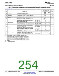
Table 8-75. Switching Characteristics Over Recommended Operating Conditions for
MMC/SD/SDIO (continued)
(see Figure 8-85 through Figure 8-88)
OPP100/OPP120/
Turbo/Nitro
MODES
NO.
PARAMETER
UNIT
3.3 V STD
1.8 V SDR12
3.3 V HS
1.8 V SDR25
MIN
MAX
MIN
MAX
11 tr(CLK)
12 tf(CLK)
Rise time, All Signals (10% to 90%)
2.2
2.2
2.2
2.2
ns
ns
Fall time, All Signals (10% to 90%)
Delay time, SD_CLK rising clock edge to SD_CMD
transition
13 td(CLKL-CMD)
14 td(CLKL-DAT)
-4
-4
4
4
2.3
2.3
14
14
ns
ns
Delay time, SD_CLK rising clock edge to SD_DATx
transition
10
7
9
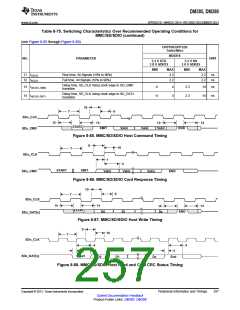
SDx_CLK
SDx_CMD
13
13
13
Valid
13
START
XMIT
Valid
Valid
END
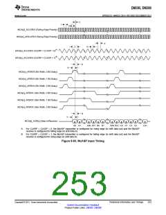
Figure 8-85. MMC/SD/SDIO Host Command Timing
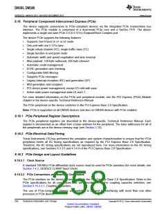
9
10
7
SDx_CLK
SDx_CMD
1
2
Valid
START
XMIT
Valid
Valid
END
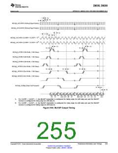
Figure 8-86. MMC/SD/SDIO Card Response Timing
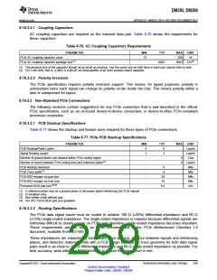
10
9
7
SDx_CLK
14
14
14
14
Dx
START
D0
D1
END
SDx_DAT[x]
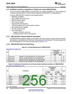
Figure 8-87. MMC/SD/SDIO Host Write Timing
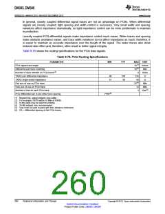
9
10
7
SDx_CLK
4
4
3
3
Start
SDx_DAT[x]
D0
D1
Dx
End
Figure 8-88. MMC/SD/SDIO Host Read and Card CRC Status Timing
Copyright © 2013, Texas Instruments Incorporated
Peripheral Information and Timings
257
Submit Documentation Feedback
Product Folder Links: DM385 DM388

 TI [ TEXAS INSTRUMENTS ]