DM385, DM388
www.ti.com
NO.
SPRS821D –MARCH 2013–REVISED DECEMBER 2013
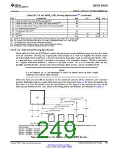
Table 8-70. CK and ADDR_CTRL Routing Specification(1)(2) (continued)
PARAMETER
MIN
4w
TYP
MAX
UNIT
16 Center-to-center CK to other DDR3 trace spacing(9)
17 Center-to-center ADDR_CTRL to other DDR3 trace spacing(9)(10)
18 Center-to-center ADDR_CTRL to other ADDR_CTRL trace spacing(9)
19 CK center-to-center spacing(11)
4w
3w
20 CK spacing to other net(9)
21 Rcp(12)
22 Rtt(12)(13)
4w
Zo-1
Zo-5
Zo
Zo
Zo+
Ω
Ω
Zo+5
(9) Center-to-center spacing is allowed to fall to minimum (2w) for up to 1250 mils of routed length.
(10) The ADDR_CTRL net class of the other DDR EMIF is considered other DDR3 trace spacing.
(11) CK spacing set to ensure proper differential impedance.
(12) Source termination (series resistor at driver) is specifically not allowed.
(13) Termination values should be uniform across the net class.
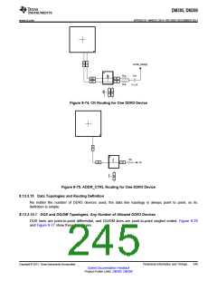
8.13.3.16.2 DQS and DQ Routing Specification
Skew within the DQS and DQ/DM net classes directly reduces setup and hold margin and thus this skew
must be controlled. The only way to practically match lengths on a PCB is to lengthen the shorter traces
up to the length of the longest net in the net class and its associated clock. As with CK and ADDR_CTRL,
a reasonable trace route length is to within a percentage of its Manhattan distance. DQLMn is defined as
DQ Longest Manhattan distance n, where n is the byte number. For a 32-bit interface, there are four
DQLMs, DQLM0-DQLM3. Likewise, for a 16-bit interface, there are two DQLMs, DQLM0-DQLM1.
NOTE
It is not required, nor is it recommended, to match the lengths across all bytes. Length
matching is only required within each byte.
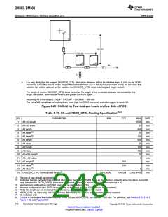
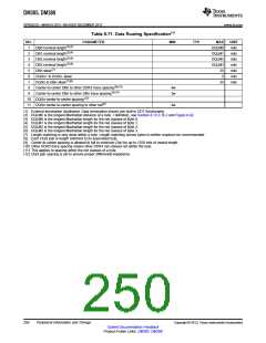
Given the DQS and DQ/DM pin locations on the processor and the DDR3 memories, the maximum
possible Manhattan distance can be determined given the placement. Figure 8-82 shows this distance for
four loads. It is from this distance that the specifications on the lengths of the transmission lines for the
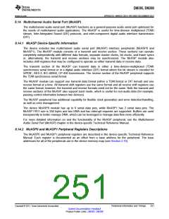
data bus are determined. For DQS and DQ/DM routing, these specifications are contained in Table 8-71.
DQLMX0
DQ[0:7]/DM0/DQS0
DB0
DQ[8:15]/DM1/DQS1
DB1
DQLMX1
DQ[16:23]/DM2/DQS2
DB2
DQLMY0
DQLMX2
DQLMY1
DQLMY3 DQLMY2
DQ[23:31]/DM3/DQS3
DB3
DQLMX3
3
2
1
0
DB0 - DB3 represent data bytes 0 - 3.
There are four DQLMs, one for each byte (32-bit interface). Each DQLM is the longest Manhattan distance of the
byte; therefore:
DQLM0 = DQLMX0 + DQLMY0
DQLM1 = DQLMX1 + DQLMY1
DQLM2 = DQLMX2 + DQLMY2
DQLM3 = DQLMX3 + DQLMY3
Figure 8-82. DQLM for Any Number of Allowed DDR3 Devices
Copyright © 2013, Texas Instruments Incorporated
Peripheral Information and Timings
249
Submit Documentation Feedback
Product Folder Links: DM385 DM388

 TI [ TEXAS INSTRUMENTS ]