DM385, DM388
www.ti.com
SPRS821D –MARCH 2013–REVISED DECEMBER 2013
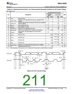
Table 8-41. Switching Characteristics Over Recommended Operating Conditions for I2C Output Timings
(see Figure 8-45)
OPP100/OPP120/Turbo/Nitro
STANDARD
NO.
PARAMETER
FAST MODE
UNIT
MODE
MIN MAX
MIN
MAX
16
17
tc(SCL)
Cycle time, SCL
10
2.5
µs
µs
Setup time, SCL high before SDA low (for a repeated START
condition)
tsu(SCLH-SDAL)
4.7
0.6
0.6
Hold time, SCL low after SDA low (for a START and a repeated
START condition)
18
th(SDAL-SCLL)
4
µs
19
20
21
22
tw(SCLL)
Pulse duration, SCL low
4.7
4
1.3
0.6
100
0
µs
µs
ns
µs
tw(SCLH)
Pulse duration, SCL high
tsu(SDAV-SCLH)
th(SCLL-SDAV)
Setup time, SDA valid before SCL high
Hold time, SDA valid after SCL low (for I2C bus devices)
250
0
3.45
0.9
Pulse duration, SDA high between STOP and START
conditions
23
24
25
26
27
tw(SDAH)
tr(SDA)
tr(SCL)
tf(SDA)
tf(SCL)
4.7
1.3
µs
ns
ns
ns
ns
20 + 0.1Cb
Rise time, SDA
Rise time, SCL
Fall time, SDA
Fall time, SCL
1000
1000
300
300
300
300
300
(1)
20 + 0.1Cb
(1)
20 + 0.1Cb
(1)
20 + 0.1Cb
300
(1)
28
29
tsu(SCLH-SDAH)
Cp
Setup time, SCL high before SDA high (for STOP condition)
Capacitance for each I2C pin
4
0.6
µs
pF
10
10
(1) Cb = total capacitance of one bus line in pF. If mixed with HS-mode devices, faster fall-times are allowed.
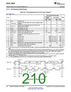
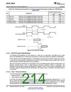
26
24
I2C[x]_SDA
21
23
19
28
20
25
I2C[x]_SCL
27
16
18
22
17
18
Stop
Start
Repeated
Start
Stop
Figure 8-45. I2C Transmit Timing
Copyright © 2013, Texas Instruments Incorporated
Peripheral Information and Timings
211
Submit Documentation Feedback
Product Folder Links: DM385 DM388

 TI [ TEXAS INSTRUMENTS ]