DM385, DM388
SPRS821D –MARCH 2013–REVISED DECEMBER 2013
www.ti.com
•
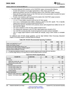
To provide adequate ESD protection on the VGA/YPbPr output, recommend the following:
–
–
–
Provide ESD protection on all output signals (that is, Video, Syncs and DDC I/F).
Minimize the distance from the ESD protection device to the VGA/YPbPr output connector.
Mount all ESD protection devices on the PCB level next to the ground plane to provide the lowest
possible impedance path to ground.
–
Provide a low impedance path to ground for the shield of the VGA/YPbPr output connector.
•
For VGA outputs, recommend the following:
–
–
3.3 V to 5 V level shifters should be used for the H/V Sync signals.
3.3 V to 5 V bi-directional level shifters should be used for the DDC signals. This is typically
implemented using two N-channel enhancement MOSFETs.
–
Recommend using the TPD7S019 ESD protection device with integrated level shifters for the H/V
Sync and DDC signals.
–
–
–
–
The source impedance of the H/V Sync outputs should be 50 Ω.
The characteristic impedance of the H/V Sync output signal traces should be 50 Ω.
The THS7360 reconstruction filter should be bypassed to provide maximum bandwidth.
The 5-V supply output should be current limited (for example, using a series resistor or resettable
fuse).
For additional video HD-DAC design guidelines, see the High Definition Video Processing Subsystem
chapter in the device-specific Technical Reference Manual.
Table 8-38. HD-DAC Recommended Operating Conditions
MIN
NOM
MAX
5
UNIT
pF
(1)
Output Load Capacitance (CLOAD
Output Load Resistors (RLOAD
Full-Scale Current Adjust Resistor (RHDDAC_IREF
)
)
–1%
–1%
–5%
–3%
165
2.67
467
4.5
+1%
+1%
+5%
+3%
Ω
)
kΩ
Optional External Voltage Reference (HDDAC_VREF)(2)
mV
V/V
Required External Amplification (THS7360)
(1) The output load capacitance includes the signal trace parasitic capacitance and the video buffer input capacitance.
(2) An external voltage reference is not required since an internal bandgap reference is provided.
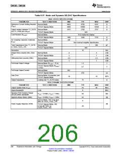
Table 8-39. HD-DAC Specifications
PARAMETER
CONDITIONS
MIN
TYP
MAX
UNIT
Resolution
10
Bits
DC Accuracy
Integral Non-Linearity (INL), best fit
Differential Non-Linearity (DNL)
2.5
1.0
LSB
LSB
Analog Output
Full-Scale Output Current (IFS)
Full-Scale Output Voltage (VFS)
Zero Scale Offset Error (ZSET)
Channel matching
DAC input = 1023
DAC input = 1023
3
494
0.5
mA
mV
LSB
%
–15%
150
+15%
2
Dynamic Specifications
Maximum Output Update Rate (FCLK)
Spurious - Free Dynamic Range (SFDR)
MHz
dB
FCLK = 74.25 MHz,
30-MHz full-scale sine wave
70
60
FCLK = 148.5 MHz,
dB
30-MHz full-scale sine wave
208
Peripheral Information and Timings
Copyright © 2013, Texas Instruments Incorporated
Submit Documentation Feedback
Product Folder Links: DM385 DM388

 TI [ TEXAS INSTRUMENTS ]