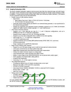
DM385, DM388
SPRS821D –MARCH 2013–REVISED DECEMBER 2013
www.ti.com
8.12 Imaging Subsystem (ISS)
The device Imaging Subsystem captures and processes pixel data from external image and video inputs.
The inputs can be connected to the Image Processing block through the Parallel Camera Interface (CAM).
In addition, a Timing control module provides flash strobe and mechanical shutter interfaces. The features
of each component of the ISS are described below.
•
Parallel Camera (CAM) interface features:
–
Input format
•
•
Bayer pattern Raw (up to 16bit) or YCbCr 422 (8-bit or 16-bit) data.
ITU-R BT.656/1120 standard format
–
–
Generates HD/VD timing signals and field ID to an external timing generator, or can synchronize to
the external timing generator.
Support for progressive and interlaced sensors (hardware support for up to 2 fields and firmware
supports for higher number of fields, typically 3-, 4-, and 5-field sensors.
•
CSI2 Serial Connection features:
–
Supports up to 1Gb/s data-rate per lane for 1, 2, and 3 Data-lane configurations, and up to
824Mbps per lane for a 4 Data-lane configuration
–
–
–
–
–
–
–
Supports sensor capture up to 4K x 2K 10-bit Bayer @ 30fps
Supports up to four data configurable links in addition to the clock signaling
Data merger for 2-, 3-, or 4-data lane configurations
1-D and 2-D addressing mode
Supports all primary and secondary MIPI-defined formats (RGB, RAW, YUV, and more)
DPCM decompression
Image cropping and A-Law/DPCM compression
•
Image Sensor Interface (ISIF) features:
–
–
–
–
–
–
–
–
–
Support for up to 32K pixels (image size) in both the horizontal and vertical direction
Color space conversion for non-Bayer pattern Raw data
Digital black clamping with Horizontal/Vertical offset drift compensation
Vertical Line defect correction based on a lookup table
Color-dependent gain control and black level offset control
Ability to control output to the DDR2/DDR3/DDR3L via an external write enable signal
Down sampling via programmable culling patterns
A-law/DPCM compression
Generating 16-, 12- or 8-bit output to memory
•
•
Two independent Resizers
–
–
–
–
–
–
Providing two different sizes of outputs simultaneously on one input
Maximum line width is 5376 and 2336, respectively
YUV422 to YUV420 conversion
Data output format: RGB565, ARGB888, YUV422 co sited and YUV4:2:0 planar
Resizer Ratio: x1/4096 ~ x20
Input from memory
Timing control module features:
–
–
–
STROBE signal for flash pre-strobe and flash strobe
SHUTTER signal for mechanical shutter control
Global reset control
For more detailed information on the ISS, see the ISS Overview section, the ISS Interfaces section, and
the ISS ISP section of the device-specific Technical Reference Manual.
212
Peripheral Information and Timings
Copyright © 2013, Texas Instruments Incorporated
Submit Documentation Feedback
Product Folder Links: DM385 DM388

 TI [ TEXAS INSTRUMENTS ]