DM385, DM388
SPRS821D –MARCH 2013–REVISED DECEMBER 2013
www.ti.com
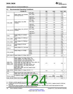
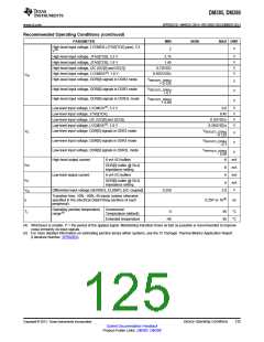
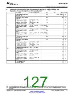
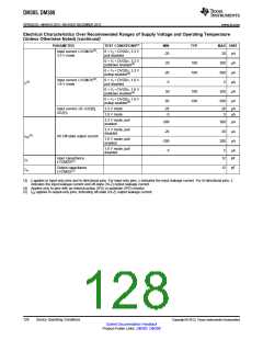
Electrical Characteristics Over Recommended Ranges of Supply Voltage and Operating Temperature
(Unless Otherwise Noted) (continued)
PARAMETER
TEST CONDITIONS(1)
MIN
TYP
MAX UNIT
Input current, LVCMOS(2)
3.3 V mode
,
0 < VI < DVDDx, 3.3 V
pull disabled
-20
20
300
-300
5
µA
µA
µA
µA
µA
µA
0 < VI < DVDDx, 3.3 V
pulldown enabled(4)
20
-20
-5
100
0 < VI < DVDDx, 3.3 V
pullup enabled(4)
-100
Input current, LVCMOS(2)
1.8 V mode
,
0 < VI < DVDDx, 1.8 V
pull disabled
II(3)
0 < VI < DVDDx, 1.8 V
pulldown enabled(4)
50
100
200
-200
0 < VI < DVDDx, 1.8 V
pullup enabled(4)
-50
-100
Input current, I2C (I2C[0],
I2C[1])
3.3 V mode
1.8 V mode
-20
-5
20
5
µA
µA
3.3 V mode, pull
enabled
-300
-20
-200
-5
300
20
µA
µA
µA
3.3 V mode, pull
disabled
(5)
IOZ
I/O Off-state output current
1.8 V mode, pull
enabled
200
1.8 V mode, pull
disabled
5
µA
pF
Input capacitance
LVCMOS(2)
12
CI
Output capacitance
LVCMOS(2)
12
pF
Co
(3) II applies to input-only pins and bi-directional pins. For input-only pins, II indicates the input leakage current. For bi-directional pins, II
indicates the input leakage current and off-state (Hi-Z) output leakage current.
(4) Applies only to pins with an internal pullup (IPU) or pulldown (IPD) resistor.
(5) IOZ applies to output-only pins, indicating off-state (Hi-Z) output leakage current.
128
Device Operating Conditions
Copyright © 2013, Texas Instruments Incorporated
Submit Documentation Feedback
Product Folder Links: DM385 DM388

 TI [ TEXAS INSTRUMENTS ]