DM385, DM388
SPRS821D –MARCH 2013–REVISED DECEMBER 2013
www.ti.com
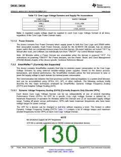
Table 7-2. Core Logic Voltage Domains and Supply Pin Associations
CORE LOGIC
SUPPLY PIN NAME
VOLTAGE DOMAIN
ARM_L
CORE_L
HDVICP_L
CVDD_ARM
CVDD
CVDD_HDVICP
Note: A regulated supply voltage must be supplied to each Core Logic Voltage Domain at all times,
regardless of the Core Logic Power Domain states.
7.2.1.2 Power Domains
The device contains four Power Domains which supply power to both the Core Logic and SRAM within
their associated modules. Each Power Domain, except for the ALWAYS ON domain, has an internal
power switch that can completely remove power from that domain. All power switches are turned "OFF" by
default after reset, and software can individually turn them "ON/OFF" via Control Module registers.
Note: All Modules within a Power Domain are unavailable when the domain is powered "OFF". For
instructions on powering "ON/OFF" the Power domains, see the Power, Reset, and Clock Management
(PRCM) Module chapter of the device-specific Technical Reference Manual.
7.2.2 SmartReflex™ [Currently Not Supported]
The device contains SmartReflex modules that help to minimize power consumption on the Core Logic
Voltage Domains by using external variable-voltage power supplies. Based on the device process,
temperature, and desired performance, the SmartReflex modules advise the host processor to raise or
lower the supply voltage to each domain for minimal power consumption.
The communication link between the host processor and the external regulators is a system-level decision
and can be accomplished using GPIOs, I2C, SPI, or other methods. The following sections briefly
describe the two major techniques employed by SmartReflex: Dynamic Voltage Frequency Scaling
(DVFS) and Adaptive Voltage Scaling (AVS).
7.2.2.1 Dynamic Voltage Frequency Scaling (DVFS) [Currently Supports Only Discrete OPPs]
Each device Core Logic Voltage Domain can be run independently at one of several Operating
Performance Points (OPPs). An OPP for a specific Core Logic Voltage Domain is defined by: (1)
maximum frequencies of operation for Modules within the Domain and (2) an associated supply voltage
range. Trading off power versus performance, OPPs with lower maximum frequencies also have lower
voltage ranges for power savings.
The OPP for a domain can be changed in real-time without requiring a reset. This feature is called
Dynamic Voltage Frequency Scaling (DVFS) Table 7-3 contains a list of voltage ranges and maximum
module frequencies for the OPPs of each Core Logic Voltage Domain.
NOTE
Not all devices support all OPP frequencies.
OPP100 is currently supported only on DM388 commercial temperature devices.
130
Power, Reset, Clocking, and Interrupts
Copyright © 2013, Texas Instruments Incorporated
Submit Documentation Feedback
Product Folder Links: DM385 DM388

 TI [ TEXAS INSTRUMENTS ]