DLPA2000
ZHCSCO5B –JUNE 2014–REVISED FEBRUARY 2018
www.ti.com.cn
7.3 Feature Description
7.3.1 DMD Regulators
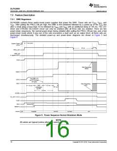
DLPA2000 contains three switch-mode power supplies that power the DMD. These rails are VOFS, VBIAS, and
VRST. After pulling the PROJ_ON pin high, the DMD is first initialized followed by a power-up of the VOFS line
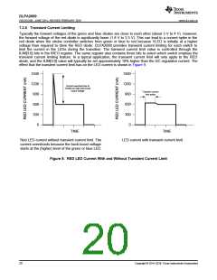
after a small delay of less than 10 ms followed by VBIAS and VRST with an additional delay of 145 ms. The LED
driver and STROBE DECODER circuit can only be enabled after all three rails are enabled. There are two
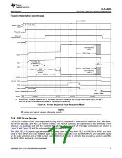
power-down sequences, the normal power-down timing initiated after pulling the PROJ_ON pin low, and a fast
power-down mode where if any one of the rails encounters a fault such as an output short, all three rails are
discharged simultaneously. The detailed power-up and power-down diagrams are shown in Figure 5 and
Figure 6.
5 ms (min)
System Power
(VINx)
10 ms
25 ms
PROJ_ON
DMD_EN
in register 0x01h
V2V5
Stop Regulating
VBIAS
VBIAS
Pad DMD_EN
by DPP through
VOFS
SPI write
VRST
Stop Regulating
VRST
10 ms
DMD
initialization
by DPP
≤ 10 ms
145 ms
≥10 ms
VCORE
LS_OUT (1.8 V)
VLED
INTZ
Startup DPP
RESETZ
ACTIVE1
OFF
STANDBY
ACTIVE2
OFF
STATE
Figure 5. Power Sequence Normal Shutdown Mode
NOTE
All values are typical (unless otherwise noted).
16
Copyright © 2014–2018, Texas Instruments Incorporated

 TI [ TEXAS INSTRUMENTS ]