CC1110Fx / CC1111Fx
configure and control OUT endpoints. Each IN
and OUT endpoint can be configured as either
the top of the endpoint memory region while
the OUT FIFO grows up from the bottom of the
endpoint memory region.
Isochronous
(USBCSIH.ISO=1
and/or
Bulk/Interrupt
and/or
USBCSOH.ISO=1)
(USBCSIH.ISO=0
USBCSOH.ISO=0)
or
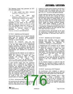
When the IN or OUT endpoint of an endpoint
number use double buffering, the sum of
USBMAXI and USBMAXO must not exceed half
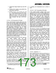
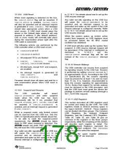
the FIFO size for the endpoint. Figure 44 b)
illustrates the IN and OUT FIFO memory for an
endpoint that uses double buffering. Notice
that the second OUT buffer starts from the
middle of the memory region and grows
upwards. The second IN buffer also starts from
the middle of the memory region but grows
downwards.
endpoints.
Bulk
and
Interrupt endpoints are handled identically by
the USB controller but will have different
properties from a firmware perspective.
The USBINDEXregister must have the value of
the endpoint number before the Indexed
Endpoint Registers are accessed (see Table
35 on Page 53).
To configure an endpoint as IN only, set
USBMAXOto 0 and to configure an endpoint as
OUT only, set USBMAXIto 0.
12.16.6.1 FIFO Management
Each endpoint has a certain number of FIFO
memory bytes available for incoming and
outgoing data packets. Table 60 shows the
FIFO size for endpoints 1 - 5. It is the firmware
that is responsible for setting the USBMAXIand
USBMAXO registers correctly for each endpoint
to prevent data from being overwritten.
For unused endpoints, both USBMAXO and
USBMAXIshould be set to 0.
EP Number FIFO Size (in bytes)
1
2
3
4
5
32
64
When both the IN and the OUT endpoint of an
endpoint number do not use double buffering,
the sum of USBMAXI and USBMAXO must not
exceed the FIFO size for the endpoint. Figure
44 a) shows how the IN and OUT FIFO
memory for an endpoint is organized with
single buffering. The IN FIFO grows down from
128
256
512
Table 60: FIFO Sizes for EP{1 - 5}
0
0
IN FIFO
(Buffer 1)
IN FIFO
USBMAXI - 1
USBMAXI - 1
USBMAX0 - 1
OUT FIFO
(Buffer 2)
0
0
IN FIFO
(Buffer 2)
USBMAXI - 1
USBMAX0 - 1
USBMAX0 - 1
OUT FIFO
(Buffer 1)
OUT FIFO
0
0
b)
a)
Figure 44: IN/OUT FIFOs, a) Single Buffering b) Double Buffering
12.16.6.2 Double Buffering
endpoints, which are expected to transfer one
data packet every USB frame without any
retransmission. For isochronous endpoint one
data packet will be sent/received every USB
frame. However, the data packet may be
sent/received at any time during the USB
frame period and there is a chance that two
To enable faster transfer and reduce the need
for retransmissions, CC1111Fx implements
double buffering, allowing two packets to be
buffered in the FIFO in each direction. This is
highly
recommended
for
isochronous
SWRS033H
Page 174 of 246

 TI [ TEXAS INSTRUMENTS ]