CC1110Fx / CC1111Fx
accessed. See 12.1.5.1 for details on how to
set up the crystal oscillator.
SLEEP.USB_EN to 0 will reset the USB
controller.
12.16.2 USB Enable
12.16.3 USB Interrupts
The USB Controller must be enabled before it
is used. This is performed by setting the
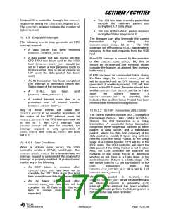
There are 3 interrupt flag registers with
associated interrupt enable mask registers.
SLEEP.USB_EN
bit
to
1.
Setting
Interrupt Flag
Description
Associated Interrupt
Enable Mask Register
Contains flags for common USB interrupts
USBCIF
USBIIF
USBCIE
USBIIE
Contains interrupt flags for endpoint 0 and all the IN
endpoints
Contains interrupt flags for all OUT endpoints
USBOIF
USBOIE
Note: All interrupts except SOF and suspend are initially enabled after reset
Table 59: USB Interrupt Flags Interrupt Enable Mask Registers
In addition to the interrupt flags in the registers
12.16.3.1 USB Resume Interrupt
shown in Table 59, there are two CPU interrupt
flags associated with the USB controller;
IRCON2.USBIF and IRCON.P0IF. For an
interrupt request to be generated, IEN1.P0IE
and/or IEN2.USBIEmust be set to 1 together
with the desired interrupt enable bits from the
USBCIE, USBIIE, and USBOIE registers.
When an interrupt request has been
generated, the CPU will start executing the
ISR if there are no higher priority interrupts
pending. The USB controller uses interrupt #6
for USB interrupts. This interrupt number is
shared with Port 2 inputs, hence the interrupt
routine must also handle Port 2 interrupts if
they are enabled. The interrupt routine should
read all the interrupt flag registers and take
action depending on the status of the flags.
The interrupt flag registers will be cleared
when they are read and the status of the
individual interrupt flags should therefore be
saved in memory (typically in a local variable
on the stack) to allow them to be accessed
multiple times.
P0_7 does not exist on the CC1111Fx, but the
corresponding interrupt is used for USB
resume interrupt. This means that to be able to
wake up the CC1111Fx from PM1/suspend when
resume signaling has been detected on the
USB bus, IEN1.P0IE must be set to 1
together
with
PICTL.P0IENH.
PICTL.P0ICONmust be 0 to enable interrupts
on rising edge. The P0 ISR should check the
P0IFG.USB_RESUME, and resume if this bit is
set to 1. If PM1 is entered from within an ISR
due to a suspend interrupt, it is important that
the priority of the P0 interrupt is set higher than
the priority of the interrupt from which PM1
was entered. See Section 12.16.9 for more
details about suspend and resume.
12.16.4 Endpoint 0
Endpoint 0 (EP0) is a bi-directional control
endpoint and during the enumeration phase all
communication is performed across this
endpoint. Before the USBADDR register has
been set to a value other than 0, the USB
controller will only be able to communicate
through endpoint 0. Setting the USBADDR
register to a value between 1 and 127 will
bring the USB function out of the Default state
in the enumeration phase and into the Address
state. All configured endpoints will then be
available for the application.
At the end of the ISR, after the interrupt flags
have been read, the interrupt flags should be
cleared to allow for new USB/P2 interrupts to
be detected. The port 2 interrupt status flags in
the P2IFG register should be cleared prior to
clearing IRCON2.P2IF(see Section 10.5.2).
Refer to Table 39 and Table 40 for a complete
list of interrupts, and Section 10.5 for more
details about interrupts.
The EP0 FIFO is only used as either IN or
OUT and double buffering is not provided for
endpoint 0. The maximum packet size for
endpoint 0 is fixed at 32 bytes.
SWRS033H
Page 171 of 246

 TI [ TEXAS INSTRUMENTS ]