CC1110Fx / CC1111Fx
12.16 USB Controller
Appropriate response to USB interrupts and
Note: The USB controller is only available
on the CC1111Fx.
loading/unloading
of
packets
into/from
endpoint FIFOs is the responsibility of the
firmware. The firmware must be able to reply
correctly to all standard requests from the USB
host and work according to the protocol
implemented in the driver on the PC.
The CC1111Fx contains a Full-Speed USB 2.0
compatible
USB
controller
for
serial
communication with a PC or other equipment
with USB host functionality.
The USB Controller has the following features:
Full-Speed operation (up to 12 Mbps)
Note: This section will focus on describing
the functionality of the USB controller, and
it is assumed that the reader has a good
understanding of USB and is familiar with
the terms and concepts used. Refer to the
Universal Serial Bus Specification for
details [6].
5 endpoints (in addition to endpoint 0)
that can be used as IN, OUT, or IN/OUT
and can be configured as bulk/interrupt
or isochronous.
1 KB SRAM FIFO available for storing
USB packets
Standard USB nomenclature is used
regarding IN and OUT. I.e., IN is always
into the host (PC) and OUT is out of the
host (into the CC1111Fx)
Endpoints supporting packet sizes from
8 – 512 bytes
Support for double buffering of USB
packets
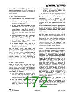
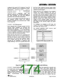
Figure 43 shows a block diagram of the USB
controller. The USB PHY is the physical
interface with input and output drivers. The
USB SIE is the Serial Interface Engine which
controls the packet transfer to/from the
endpoints. The USB controller is connected to
the rest of the system through the Memory
Arbiter.
The USB controller monitors the USB bus for
relevant activity and handles packet transfers.
The CC1111Fx will always operate as a slave on
the USB bus and responds only on requests
from the host (a packet can only be sent (or
received) when the USB host sends a request
in the form of a token).
USB Controller
EP0
EP1
DP
EP2
Memory
USB PHY
USB SIE
Arbiter
EP3
DM
EP4
EP5
1 KB
SRAM
(FIFOs)
Figure 43: USB Controller Block Diagram
12.16.1 48 MHz Clock
generate a maximum system clock frequency
of 24 MHz. It is important that the crystal
oscillator is stable before the USB Controller is
A 48 MHz external crystal must be used for the
USB Controller to operate correctly. This 48
MHz clock is divided by two internally to
SWRS033H
Page 170 of 246

 TI [ TEXAS INSTRUMENTS ]