CC1110Fx / CC1111Fx
12.15.8.2 Word Size
12.15.11 Word Counter
The word size must be set before master
mode is enabled. The word size is the number
of bits used for each sample and can be set to
a value between 1 and 33. To set the word
The I2S contains a 10-bit word counter, which
is counting transitions on the WS line. The
counter can be cleared by triggers or by writing
to the I2SWCNT register. When a trigger
occurs, or a value is written to I2SWCNT, the
current value of the word counter is copied into
the
size, write word size
–
1
to the
I2SCFG1.WORDS[4:0] bits. Setting the word
size to a value of 17 or more causes the I2S to
pad each word with 0’s in the least significant
bits since the data registers provide maximum
16 bits. This feature allows samples to be sent
to an I2S device that takes a higher resolution
than 16 bits.
I2SSTAT.WCNT[9:8]:I2SWCNT.WCNT[7:0]regi
sters and the word counter is cleared.
Three triggers can be used to copy/clear the
word counter.
USB SOF: USB Start of Frame. Occurs
every ms (CC1111Fx only)
If the size of the received samples exceeds 16
bits, only the 16 most significant bits will be put
in the data registers and the remaining low
order bits will be discarded.
T1_CH0: Timer 1, compare, channel 0
IOC_1: IO pin input transition (P1_3)
Which trigger to use is configured through the
TRIGNUMfield in the I2SCFG1register. When
the I2S is configured not to use any trigger
(I2SCFG1.TRIGNUM=0), the word counter can
only be copied/cleared from software.
12.15.9 Slave Mode
The I2S is configured as a slave device by
setting I2SCFG0.MASTER to 0. When in slave
mode the SCK and WS signals are generated
by an external I2S master and are inputs to the
I2S interface.
The word counter will saturate if it reaches its
maximum value. Software should configure the
trigger-interval and sample-rate to ensure this
never happens.
12.15.9.1 Word Size
When the I2S operates in slave mode, the word
size is determined by the master that
generates the WS signal.
The I2S will provide bits from the internal 16-bit
buffer until the buffer is empty. If the buffer
becomes empty and the master still requests
more bits, the I2S will send 0’s (low order bits).
CC1111Fx: The word counter is typically used to
calculate the average sample rate over a long
period of time (e.g. 1 second) needed by
adaptive isochronous USB endpoints. The
USB SOF event must then be used as trigger.
12.15.12 µ-Law Compression and Expansion
If more than 16 bits are being received, the low
order bits are discarded.
The I2S interface can be configured to perform
μ-Law compression and expansion. µ-Law
compression is enabled by setting the
I2SCFG0.ULAWC bit to
1
and µ-Law
12.15.10 Mono
expansion is enabled by setting the
I2SCFG0.ULAWEbit to 1.
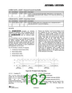
The I2S also supports mono audio samples.
To receive mono samples, I2SCFG0.RXMONO
should be set to 1. Words from the right
channel will then not be read into the data
registers. This feature is included because
some mono devices repeat their audio data in
both channels and the left channel is the
default mono channel.
When the I2S interface is enabled, i.e. the
I2SCFG0.ENABbit is 1, and µ-Law expansion
is enabled, every byte of μ-Law compressed
data written to the I2SDATH register is
expanded to a 16-bit sample before being
transmitted. When the I2S interface is enabled
and µ-Law compression is enabled each
sample received is compressed to an 8-bit μ-
Law sample and put in the I2SDATHregister.
When the I2S interface is disabled, i.e. the
I2SCFG0.ENAB bit is 0, it can still be used to
perform μ-Law compression/expansion for
other resources in the system. To perform an
expansion, I2SCFG0.ULAWE must be 1 and
To send mono samples, I2SCFG0.TXMONO
should be set to 1. Each word will then be
repeated in both channels before a new word
is fetched from the data registers. This is to
enable sending a mono audio signal to a
stereo audio sink device.
SWRS033H
Page 165 of 246

 TI [ TEXAS INSTRUMENTS ]