CC1110Fx / CC1111Fx
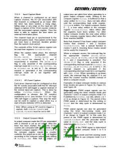
to generate a PWM output signal (see Figure
32 and Figure 33).
selected. The channel output compare mode 3
or 4 (defined by T1CCTLn.CMPbits, where nis
1 or 2) is selected depending on required
polarity of the PWM signal (see Figure 34).
The period of the PWM signal is determined by
T1CC0 and the duty cycle for the channel
output is determined by T1CCn(n= 1 or 2).
The polarity of the PWM signal is determined
by whether output compare mode 3 or 4 is
used.
Centre-aligned: PWM outputs can be
generated when the timer up/down mode is
0xFFFF
T1CC0
T1CCn
0x0000
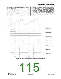
0: Set output on compare
1: Clear output on compare
2: Toggle output on compare
3: Set output on compare-up,
clear on 0
4: Clear output on compare-up,
set on 0
5: Set when T1CCn,
clear when T1CC0
6: Clear when T1CCn,
set when T1CC0
T1CCn
T1CC0
T1CCn
T1CC0
Figure 32: Output Compare Modes, Timer Free-running Mode
SWRS033H
Page 115 of 246

 TI [ TEXAS INSTRUMENTS ]