CC1110Fx / CC1111Fx
12.6.8
DSM Mode
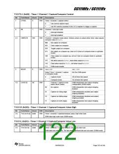
set together with IEN1.T1EN. The interrupt
mask bits are T1CCTL0.IM, T1CCTL1.IM,
T1CCTL2.IM, and TIMIF.OVFIM. Note that
enabling an interrupt mask bit will generate a
new interrupt request if the corresponding
interrupt flag is set.
Timer 1 also contains a 1-bit Delta-Sigma
Modulator (DSM) of second order that can be
used to produce a mono audio output PWM
signal. The DSM removes the need for high
order external filtering required when using
regular PWM mode.
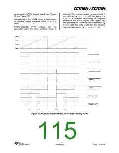
When the timer is used in Free-running Mode
or Modulo Mode the interrupt flags are set as
follows:
The DSM operates at a fixed speed of either
1/4 or 1/8 of the timer tick speed set by
CLKCON.TICKSPD. The DSM speed is set by
T1CCTL1.MODE. The input samples are
updated at a configurable sampling rate set by
the terminal count value T1CC0.
T1CTL.CH0IF, T1CTL.CH1IF, and
T1CTL.CH2IF
are
set
on
compare/capture event
T1CTL.OVFIF is set when counter
An interpolator is used to match the sampling
rate with the DSM update rate. This
interpolator is of first order with a scaling
compensation. The scaling compensation is
due to variable gain defined by the difference
in sampling speed and DSM speed. This
interpolation mechanism can be disabled by
reaches terminal count value (overflow)
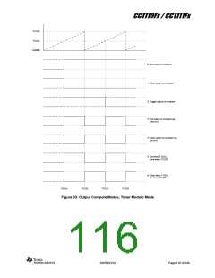
When the timer is used in Up/Down Mode the
interrupt flags are set as follows:
In compare mode:
T1CTL.CH0IF
and
T1CTL.OVFIF
are set when counter turns around on
zero
setting
T1CCTL1.CAP=10
or
T1CCTL1.CAP=11, thus using a zeroth order
interpolator.
T1CTL.CH1IF
and
T1CTL.CH2IF
In addition to the interpolator, a shaper can be
used to account for differences in rise/fall times
in the output signal. Also the shaper is
enabled/disabled using the two CAP bits in the
T1CCTL1 register. This shaper ensures a
rising and a falling edge per bit and will thus
limit the output swing to 1/8 to 7/8 of I/O VDD
when the DSM operates at 1/8 of the timer tick
speed or 1/4 to 3/4 of I/O VDD when the DSM
operates at 1/4 of the timer tick speed.
are set on compare event
In capture mode:
T1CTL.OVFIF is set when counter
turns around on zero
T1CTL.CH0IF, T1CTL.CH1IF, and
T1CTL.CH2IF are set on capture event
I addition, the CPU interrupt flag, IRCON.T1IF
will be asserted if the channel n interrupt mask
bit (T1CCTLn.IM) is set to 1.
The DSM is used as in PWM mode where the
terminal count value T1CC0 defines the
period/sampling rate. The DSM can not use
the Timer 1 prescaler to further slow down the
period.
12.6.7
Timer 1 DMA Triggers
There are three DMA triggers associated with
Timer 1, one for each channel. These are DMA
triggers T1_CH0, T1_CH1 and T1_CH2, which
are generated on timer capture/compare
events as follows:
Timer 1 must be configured to operate in
modulo mode (T1CTL.MODE=10) and channel
0 must be configured to compare mode
(T1CCTL0.MODE=1). The terminal count value
T1CC0, held in the registers T1CC0H:T1CC0L,
defines the sample rate. Table 53 shows some
T1CC0 settings for different sample rates
(CLKCON.TICKSPD=000).
T1_CH0 - Channel 0 capture/compare
T1_CH1 - Channel 1 capture/compare
T1_CH2 - Channel 2 capture/compare
SWRS033H
Page 118 of 246

 TI [ TEXAS INSTRUMENTS ]