CC1110Fx / CC1111Fx
Sample Rate
T1CC0H T1CC0L
8 kHz @ 24 MHz
8 kHz @ 26 MHz
0x0B
0x0C
0xB7
0xB1
0xDB
0x59
0xF3
0x1D
0x76
0x96
16 kHz @ 24 MHz 0x05
16 kHz @ 26 MHz 0x06
48 kHz @ 24 MHz 0x01
48 kHz @ 26 MHz 0x02
64 kHz @ 24 MHz 0x01
64 kHz @ 26 MHz 0x01
Table 53: Channel 0 Period Setting for some Sampling Rates (CLKCON.TICKSPD=000)
Since the DSM starts immediately after DSM
mode has been enabled by setting
T1CCTL1.CMP=111, all configuration should
have been performed prior to enabling DSM
mode. Also, the Timer 1 counter should be
cleared and started just before starting the
DSM operation (all write accesses to the
T1CNTL register will reset the 16-bit counter
while writing a value other than 00 to
T1CTL.MODE will start the counter). A simple
procedure for setting up DSM mode should
then be as follows:
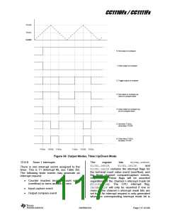
On each Timer 1 IRQ or Timer 1 DMA trigger,
write a new sample to the T1CC1H:T1CC1L
registers. The least significant bits must be
written to T1CC1L before the most significant
bits are written to T1CC1H.
The samples written must be signed 2’s
complement values. The 2 least significant bits
will always be treated as 0, thus the effective
sample size is 14 bits.
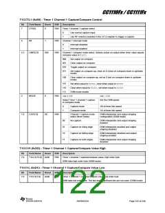
12.6.9
Timer 1 Registers
1. Suspend timer 1 (T1CTL.MODE=00)
This section describes the following Timer 1
registers:
2. Clear timer counter by writing any value
to T1CNTL, (CNT=0x0000)
T1CNTH- Timer 1 Counter High
T1CNTL- Timer 1 Counter Low
T1CTL- Timer 1 Control and Status
3. Set the sample rate by writing to T1CC0.
4. Set Timer 1 channel 0 compare mode
(T1CCTL0.MODE=1)
T1CCTLn
-
Timer
1
Channel
n
n
n
5. Load first sample if available (or zero if
Capture/Compare Control
no
sample
available)
into
T1CCnH Timer
Capture/Compare Value High
-
1
Channel
T1CC1H:T1CC1L.
6. Set timer operation to modulo mode
T1CCnL Timer Channel
1
(T1CTL.MODE=10)
Capture/Compare Value Low
7. Configure the DSM by setting the MODE
and CAP fields of the T1CCTL1register.
The TIMIF register is described in Section
12.9.8.
8. Enable
DSM
mode
(T1CCTL1.CMP=111)
SWRS033H
Page 119 of 246

 TI [ TEXAS INSTRUMENTS ]