CC1110Fx / CC1111Fx
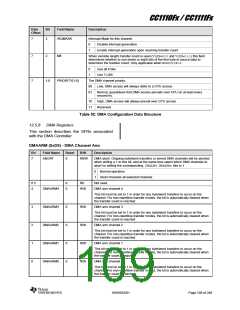
0xFFFF
0x0000
OVFIF = 1
OVFIF = 1
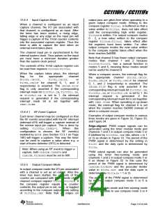
Figure 29: Free-running Mode
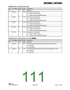
12.6.2.2 Modulo Mode
T1CTL.OVFIF flag is set. The IRCON.T1IF
flag is only asserted if the corresponding
interrupt mask bit TIMIF.OVFIM is set. An
interrupt request is generated when both
TIMIF.OVFIM and IEN1.T1EN are set to 1.
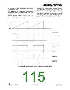
The modulo mode can be used for
applications where a period other than 0xFFFF
is required.
In modulo mode the counter starts from
0x0000 and increments at each active clock
edge. When the counter reaches the terminal
count value T1CC0 (overflow), held in the
registers T1CC0H:T1CC0L, the counter is
loaded with 0x0000 on the next timer tick and
continues incrementing its value as shown in
Figure 30. When T1CC0 is reached, the
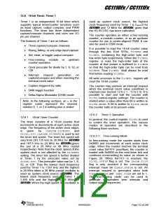
T1CC0
0x0000
OVFIF = 1
OVFIF = 1
Figure 30: Modulo Mode
flag is set. The IRCON.T1IF flag is only
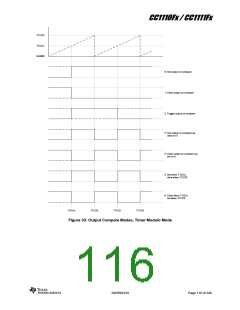
12.6.2.3 Up/Down Mode
asserted if the corresponding interrupt mask
bit TIMIF.OVFIM is set. An interrupt request
is generated when both TIMIF.OVFIM and
IEN1.T1EN are set to 1. The up/down mode
can be used when symmetrical output pulses
are required with a period other than 0xFFFF,
and therefore allows implementation of centre-
aligned PWM output applications.
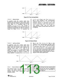
In up/down mode the counter starts from
0x0000 and increments at each active clock
edge. When the counter value matches the
terminal count value T1CC0, held in the
registers T1CC0H:T1CC0L, the counter counts
down until 0x0000 is reached and it starts
counting up again as shown in Figure 31.
When 0x0000 is reached, the T1CTL.OVFIF
T1CC0
0x0000
OVFIF = 1
OVFIF = 1
Figure 31: Up/Down Mode
Note: Before an I/O pin can be used by the
12.6.3
Channel Mode Control
timer, the required I/O pin must be configured
as a Timer 1 peripheral pin as described in
Section 12.4.6 on Page 91 .
The channel mode is set with each channel’s
control and status register T1CCTLn. The
settings include input capture and output
compare modes.
SWRS033H
Page 113 of 246

 TI [ TEXAS INSTRUMENTS ]