CC1110Fx / CC1111Fx
12.6 16-bit Timer, Timer 1
Timer 1 is an independent 16-bit timer which
supports typical timer/counter functions such
as input capture, output compare, and PWM
functions. The timer has three independent
capture/compare channels and uses one I/O
pin per channel.
used as system clock source, the highest
clock frequency used by Timer 1 is fXOSC/2 for
CC1110Fx and 12 MHz for CC1111Fx, given that
the HS RCOSC has been calibrated.
The counter operates as either a free-running
counter, a modulo counter, or as an up/down
counter for use in centre-aligned PWM. It can
also be used in DSM mode.
The features of Timer 1 are as follows:
Three capture/compare channels
It is possible to read the 16-bit counter value
through the two 8-bit SFRs; T1CNTH and
T1CNTL, containing the high-order byte and
low-order byte respectively. When the T1CNTL
register is read, the high-order byte of the
counter at that instant is buffered in T1CNTH
so that the high-order byte can be read from
T1CNTH. Thus T1CNTL shall always be read
first before reading T1CNTH.
Rising, falling, or any edge input capture
Set, clear, or toggle output compare
Free-running, modulo or up/down
counter operation
Clock prescaler for divide by 1, 8, 32, or
128
Interrupt
request
generation
on
capture/compare and when reaching the
terminal count value
All write accesses to the T1CNTL register will
reset the 16-bit counter.
Capture triggered by radio
DMA trigger function
The counter may produce an interrupt request
when the terminal count value (overflow) is
reached (see Section 12.6.2.1 - 12.6.2.3). It is
possible to start and halt the counter with
T1CTLcontrol register settings. The counter is
started when a value other than 00 is written to
T1CTL.MODE. If 00 is written to T1CTL.MODE
the counter halts at its present value.
Delta-Sigma Modulator (DSM) mode
Note: In the following sections, an n in the
register name represent the channel
number 0, 1, or 2 if nothing else is stated
12.6.2
Timer 1 Operation
12.6.1
16-bit Timer Counter
In general, the control register T1CTL is used
to control the timer operation. The various
modes of operation are described in the
following three sections.
The timer consists of a 16-bit counter that
increments or decrements at each active clock
edge. The frequency of the active clock edges
is
given
by
CLKCON.TICKSPD
and
T1CTL.DIV. CLKCON.TICKSPDis used to set
the timer tick speed. The timer tick speed will
vary from 203.125 kHz to 26 MHz for CC1110Fx
and 187.5 kHz to 24 MHz for CC1111Fx (given
the use of a 26 MHz or 48 MHz crystal
respectively). Note that the clock speed of the
system clock is not affected by the TICKSPD
setting. The timer tick speed is further divided
in Timer 1 by the prescaler value set by
T1CTL.DIV.This prescaler value can be 1, 8,
32, or 128. Thus the lowest clock frequency
used by Timer 1 is 1.587 kHz and the highest
is 26 MHz when a 26 MHz crystal oscillator is
used as system clock source (CC1110Fx). The
lowest clock frequency used by Timer 1 is
1.465 kHz and the highest is 24 MHz for
CC1111Fx. When the high speed RC oscillator is
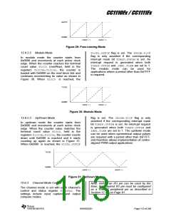
12.6.2.1 Free-running Mode
In free-running mode the counter starts from
0x0000 and increments at each active clock
edge. When the counter reaches the terminal
count value 0xFFFF (overflow), the counter is
loaded with 0x0000 on the next timer tick and
continues incrementing its value as shown in
Figure 29. When 0xFFFF is reached, the
T1CTL.OVFIF flag is set. The IRCON.T1IF
flag is only asserted if the corresponding
interrupt mask bit TIMIF.OVFIM is set. An
interrupt request is generated when both
TIMIF.OVFIM and IEN1.T1EN are set to 1.
The free-running mode can be used to
generate independent time intervals and
output signal frequencies.
SWRS033H
Page 112 of 246

 TI [ TEXAS INSTRUMENTS ]