bq24160, bq24161
bq24163, bq24168
www.ti.com
SLUSAO0A –NOVEMBER 2011–REVISED MARCH 2012
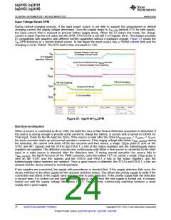
Input Overvoltage Protection
The built-in input overvoltage protection to protect the device and other downstream components against
damage from overvoltage on the input supply (Voltage from VUSB or VIN to PGND). During normal operation, if
VSUPPLY > VOVP, the bq2416x turns off the PWM converter, turns the battery FET and BGATE on, sends a single
128μs pulse is sent on the STAT and INT outputs and the STATx and FAULT_x bits of the status registers and
the battery/supply status registers are updated. Once the OVP fault is removed, the STATx and FAULT_x bits
are cleared and the device returns to normal operation.
To allow operation with some unregulated adapters, the OVP circuit is not active during Bad Source Detection.
This provides some time for the current sink to pull the unregulated adapter down into an acceptable range. If the
adapter voltage is high at the end of the detection, the startup of the PWM converter does not occur. The OVP
circuit is active during normal operation, so if the system standby current plus the charge current is not enough to
pull down the source, operation is suspended.
Charge Status Outputs (STAT, INT)
The STAT output is used to indicate operation conditions for bq2416x. STAT is pulled low during charging when
EN_STAT bit in the control register (0x02h) is set to “1”. When charge is complete or disabled, STAT is high
impedance. When a fault occurs, a 128-µs pulse (interrupt) is sent out to notify the host. The status of STAT
during different operation conditions is summarized in Table 1. STAT drives an LED for visual indication or can
be connected to the logic rail for host communication. The EN_STAT bit in the control register (00H) is used to
enable/disable the charge status for STAT. The interrupt pulses are unaffected by EN_STAT and will always be
shown. The INT output is identical to STAT and is used to interface with a low voltage host processor.
Table 1. STAT Pin Summary
Charge State
Charge in progress and EN_STAT=1
STAT and INT behavior
Low
Other normal conditions
High-Impedance
Status Changes: Supply Status Change (plug in or removal), safety timer fault,
watchdog expiration, sleep mode, battery temperature fault (TS), battery fault
(OVP or absent), thermal shutdown
128-µs pulse, then High Impedance
Good Battery Monitor
The bq2416x contains a good battery monitor circuit that places the bq2416x into high-z mode if the battery
voltage is above the BATGD threshold while in DEFAULT mode. This function is used to enable compliance to
the battery charging standard that prevents charging from an un-enumerated USB host while the battery is above
the good battery threshold. If the bq2416x is in HOST mode, it is assumed that USB host has been enumerated
and the good battery circuit has no effect on charging.
SERIAL INTERFACE DESCRIPTION
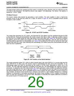
The bq2416x uses an I2C-compatible interface to program charge parameters. I2C is a 2-wire serial interface
developed by Philips Semiconductor (see I2C-Bus Specification, Version 2.1, January 2000). The bus consists of
a data line (SDA) and a clock line (SCL) with pull-up structures. When the bus is idle, both SDA and SCL lines
are pulled high. All I2C-compatible devices connect to the I2C bus through open drain I/O pins, SDA and SCL. A
master device, usually a microcontroller or a digital signal processor, controls the bus. The master is responsible
for generating the SCL signal and device addresses. The master also generates specific conditions that indicate
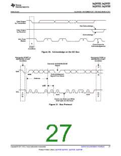
the START and STOP of data transfer. A slave device receives and/or transmits data on the bus under control of
the master device.
The bq2416x device works as a slave and supports the following data transfer modes, as defined in the I2C Bus
Specification: standard mode (100kbps) and fast mode (400kbps). The interface adds flexibility to the battery
charging solution, enabling most functions to be programmed to new values depending on the instantaneous
application requirements. Register contents remain intact as long as battery voltage remains above 2.5V
(typical). The I2C circuitry is powered from VBUS when a supply is connected. If the VBUS supply is not
connected, the I2C circuitry is powered from the battery through BAT. The battery voltage must stay above 2.5V
with no input connected in order to maintain proper operation.
Copyright © 2011–2012, Texas Instruments Incorporated
Submit Documentation Feedback
25
Product Folder Link(s): bq24160 bq24161 bq24163 bq24168

 TI [ TEXAS INSTRUMENTS ]