ADS62P49 / ADS62P29
ADS62P48 / ADS62P28
www.ti.com............................................................................................................................................................. SLAS635A–APRIL 2009–REVISED JUNE 2009
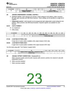
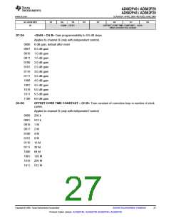
A7–A0 IN HEX
D7
D6
D5
D4
D3
D2
D1
D0
50
0
<ENABLE INDEPENDENT
CHANNEL CONTROL>
0
0
0
<DATA FORMAT>
2s complement or offset binary
0
D6
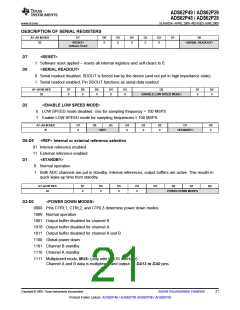
<ENABLE INDEPENDENT CHANNEL CONTROL>
0
1
Common control – both channels use common control settings for test patterns, offset correction,
fine gain, gain correction and SNR Boost functions. These settings can be specified in a single set of
registers.
Independent control – both channels can be programmed with independent control settings for test
patterns, offset correction and SNR Boost functions. Separate registers are available for each
channel.
D2-D1
<DATA FORMAT>
10 2s complement
11 Offset binary
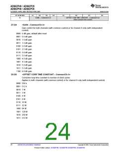
A7–A0 IN HEX
D7
D6
D5
D4
<Custom Pattern Low>
<Custom Pattern High>
D3
D2
D1
D0
51
52
0
0
D7-D0
D5-D0
<CUSTOM PATTERN LOW>
8 lower bits of custom pattern available at the output instead of ADC data.
<CUSTOM PATTERN HIGH>
6 upper bits of custom pattern available at the output instead of ADC data
Use this mode along with “Test Patterns” (register 0x62).
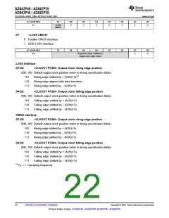
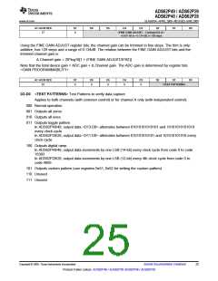
A7–A0 IN HEX
D7
D6
D5
D4
D3
D2
D1
D0
53
0
<ENABLE OFFSET CORRECTION – Common/Ch A> Offset
0
0
0
0
0
0
correction enable
D6
<ENABLE OFFSET CORRECTION – Common/Ch A>
Offset correction enable control for both channels (with common control) or for channel A only (with
independent control).
0
1
Offset correction disabled
Offset correction enabled
Copyright © 2009, Texas Instruments Incorporated
Submit Documentation Feedback
23
Product Folder Link(s): ADS62P49 / ADS62P29 ADS62P48 / ADS62P28

 TI [ TEXAS INSTRUMENTS ]