ADS131B04-Q1
ZHCSMK3B –NOVEMBER 2020 –REVISED NOVEMBER 2021
www.ti.com.cn
9.2 Typical Application
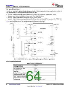
This section describes a typical battery management system (BMS) application circuit using the ADS131B04-Q1.
The device serves the following primary functions in this BMS:
• Measure battery current with high resolution and accuracy using a low-side current shunt sensor
• Measure peak currents and detect overcurrent or short-circuit conditions
• Measure battery-pack voltage using a high-voltage resistor divider
• Measure shunt temperature using a linear positive temperature coefficient (PTC) thermistor, the TMP61-Q1
图9-4 shows the front-end for the battery management system circuit design.
PACK+
AVDD = 3.3 V
DVDD = 3.3 V
AVDD
DVDD
AVDD
1 …F
1 …F
ADS131B04-Q1
RH1
RH2
RH3
R1
AIN0P
AIN0N
Supply Voltage
Measurement
R2
AIN1P
AIN1N
CLKIN
DRDY
Battery Pack Voltage
Measurement
RL
CS
SCLK
AIN2P
AIN2N
Current Shunt
Measurement
DIN
DOUT
SYNC/RESET
AVDD
RBIAS
AIN3P
AIN3N
AGND
TMP61-Q1
(PTC)
Shunt Temperature
Measurement
CAP
220 nF
PACK-
DGND
RSHUNT
图9-4. ADS131B04-Q1 in a Typical Battery Management System Application
9.2.1 Design Requirements
表9-2. Design Requirements
DESIGN PARAMETER
Current Measurement
Current measurement range
Current shunt value
Update rate
VALUE
±5 kA
35 μΩ
1 ms
Battery-Pack Voltage Measurement
Voltage measurement range
Shunt Temperature Measurement
Temperature measurement range
Thermistor type
0 V to 800 V
–40°C to +125°C
TMP61-Q1 (10-kΩPTC)
Copyright © 2022 Texas Instruments Incorporated
64
Submit Document Feedback
Product Folder Links: ADS131B04-Q1

 TI [ TEXAS INSTRUMENTS ]