ADS131B04-Q1
ZHCSMK3B –NOVEMBER 2020 –REVISED NOVEMBER 2021
www.ti.com.cn
9 Application and Implementation
Note
以下应用部分中的信息不属于TI 器件规格的范围,TI 不担保其准确性和完整性。TI 的客 户应负责确定
器件是否适用于其应用。客户应验证并测试其设计,以确保系统功能。
9.1 Application Information
9.1.1 Troubleshooting
表 9-1 lists common issues faced when designing with the ADS131B04-Q1 and the corresponding solutions.
This list is not comprehensive.
表9-1. Troubleshooting Common Issues Using the ADS131B04-Q1
ISSUE
POSSIBLE ROOT CAUSE
POSSIBLE SOLUTION
The SYNC/RESET pin functions as a
constant synchronization check, rather than a
convert start pin. See the Synchronization
section for more details on the intended
usage of the SYNC/RESET pin.
The F_RESYNC bit is set in the STATUS
word even though this bit was already
cleared.
The SYNC/RESET pin is being toggled
asynchronously to CLKIN.
The entire frame is not being sent to the
device. The device does not recognize data including those for channels that are
as being read. disabled.
Read all data words in the output data frame,
The same ADC conversion data are output
twice before changing.
9.1.2 Unused Inputs and Outputs
Leave any unused analog inputs floating or connect them to AGND.
Do not float unused digital inputs because excessive power-supply leakage current can result. Tie all unused
digital inputs to the appropriate levels, DVDD or DGND.
Tie the CLKIN pin to DGND if the internal oscillator is used.
Leave the DRDY pin unconnected if unused or connect it to DVDD using a weak pullup resistor.
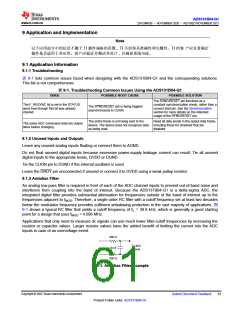
9.1.3 Antialias Filter
An analog low-pass filter is required in front of each of the ADC channel inputs to prevent out-of-band noise and
interferers from coupling into the band of interest. Because the ADS131B04-Q1 is a delta-sigma ADC, the
integrated digital filter provides substantial attenuation for frequencies outside of the band of interest up to the
frequencies adjacent to fMOD. Therefore, a single-order RC filter with a cutoff frequency set at least two decades
below the modulator frequency provides sufficient antialiasing protection in the vast majority of applications. 图
9-1 shows a typical RC filter that yields a cutoff frequency of fC = 39.8 kHz, which is generally a good starting
point for a design that uses fMOD = 4.096 MHz.
Applications that only need to measure dc signals can use much lower filter-cutoff frequencies by increasing the
resistor or capacitor values. Larger resistor values have the added benefit of limiting the current into the ADC
inputs in case of an overvoltage event.
200 ꢀ
To ADC
Inputs
10 nF
200 ꢀ
图9-1. Antialias Filter Example
Copyright © 2022 Texas Instruments Incorporated
Submit Document Feedback
61
Product Folder Links: ADS131B04-Q1

 TI [ TEXAS INSTRUMENTS ]