ADS131B04-Q1
ZHCSMK3B –NOVEMBER 2020 –REVISED NOVEMBER 2021
www.ti.com.cn
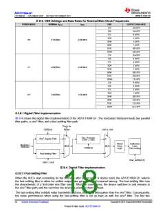
表8-4. OSR Settings and Data Rates for Nominal Main Clock Frequencies
POWER MODE
NOMINAL fMCLK
fMOD
OSR
OUTPUT DATA RATE
128
32 kSPS
16 kSPS
8 kSPS
4 kSPS
2 kSPS
1 kSPS
500 SPS
250 SPS
16 kSPS
8 kSPS
4 kSPS
2 kSPS
1 kSPS
500 SPS
250 SPS
125 SPS
8 kSPS
4 kSPS
2 kSPS
1 kSPS
500 SPS
250 SPS
125 SPS
62.5 SPS
256
512
1024
2048
4096
8192
16384
128
HR
8.192 MHz
4.096 MHz
256
512
1024
2048
4096
8192
16384
128
LP
4.096 MHz
2.048 MHz
256
512
1024
2048
4096
8192
16384
VLP
2.048 MHz
1.024 MHz
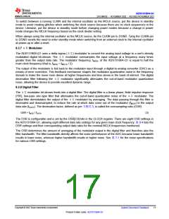
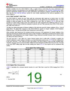
8.3.8.1 Digital Filter Implementation
图 8-4 shows the digital filter implementation of the ADS131B04-Q1. The modulator bitstream feeds two parallel
filter paths, a sinc3 filter, and a fast-settling filter path.
Power-up
or
Reset
OSR[2:0]
OSR ≤ 1024
Sinc1 Averager
(OSR > 1024)
Sinc3 Regular Filter
0
0
Calibration
Logic,
Gain scaling
Global
Chop
Logic
Modulator
Bitstream
MUX
1
MUX
1
OSR[2:0]
Fast-Settling Filter
OSR = 1024
PGA_GAINx[2:0]
图8-4. Digital Filter Implementation
8.3.8.1.1 Fast-Settling Filter
When the ADCs start converting for the first time after power-up or a device reset, the ADS131B04-Q1 selects
the fast-settling filter to allow for settled output data generation with minimal latency. The fast-settling filter has
the characteristic of a first-order sinc filter (sinc1). After two conversions, the device switches to and remains in
the sinc3 filter path until the next time the device is powered down or reset.
The fast-settling filter exhibits wider bandwidth and less stop-band attenuation than the sinc3 filter. Consequently,
the noise performance when using the fast-settling filter is not as high as with the sinc3 filter. The first two
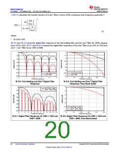
Copyright © 2022 Texas Instruments Incorporated
18
Submit Document Feedback
Product Folder Links: ADS131B04-Q1

 TI [ TEXAS INSTRUMENTS ]