ADS1299
SBAS499A –JULY 2012–REVISED AUGUST 2012
www.ti.com
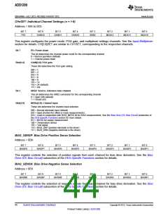
CHnSET: Individual Channel Settings (n = 1:8)
Address = 05h to 0Ch
BIT 7
PD1
BIT 6
BIT 5
BIT 4
BIT 3
SRB2
BIT 2
BIT 1
BIT 0
GAIN12
GAIN11
GAIN10
MUX12
MUX11
MUX10
This register configures the power mode, PGA gain, and multiplexer settings channels. See the Input Multiplexer
section for details. CH[2:8]SET are similar to CH1SET, corresponding to the respective channels.
Bit 7
PD: Power-down
This bit determines the channel power mode for the corresponding channel.
0 = Normal operation (default)
1 = Channel power-down
Bits[6:4]
GAIN[2:0]: PGA gain
These bits determine the PGA gain setting.
000 = 1
001 = 2
010 = 4
011 = 6
100 = 8
101 = 12
110 = 24 (default)
111 = n/a
Bit 3
SRB2: Source, reference bias channel
This bit determines the SRB2 connection for the corresponding channel.
0 = Open (off) (default)
1 = Closed (on)
Bits[2:0]
MUXn[2:0]: Channel input
These bits determine the channel input selection.
000 = Normal electrode input (default)
001 = Input shorted (for offset or noise measurements)
010 = Used in conjunction with BIAS_MEAS bit for BIAS measurements. See the Bias Drive (DC Bias Circuit) subsection of
the EEG-Specific Functions section for more details.
011 = MVDD for supply measurement
100 = Temperature sensor
101 = Test signal
110 = BIAS_DRP (positive electrode is the driver)
111 = BIAS_DRN (negative electrode is the driver)
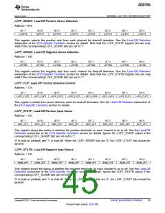
BIAS_SENSP: Bias Drive Positive Sense Selection
Address = 0Dh
BIT 7
BIT 6
BIT 5
BIT 4
BIT 3
BIT 2
BIT 1
BIT 0
BIASP8
BIASP7
BIASP6
BIASP5
BIASP4
BIASP3
BIASP2
BIASP1
This register controls the selection of positive signals from each channel for bias drive derivation. See the Bias
Drive (DC Bias Circuit) subsection of the EEG-Specific Functions section for details.
BIAS_SENSN: Bias Drive Negative Sense Selection
Address = 0Eh
BIT 7
BIT 6
BIT 5
BIT 4
BIT 3
BIT 2
BIT 1
BIT 0
BIASN8
BIASN7
BIASN6
BIASN5
BIASN4
BIASN3
BIASN2
BIASN1
This register controls the selection of negative signals from each channel for bias drive derivation. See the Bias
Drive (DC Bias Circuit) subsection of the EEG-Specific Functions section for details.
44
Submit Documentation Feedback
Copyright © 2012, Texas Instruments Incorporated
Product Folder Link(s): ADS1299

 TI [ TEXAS INSTRUMENTS ]