ADS1299
SBAS499A –JULY 2012–REVISED AUGUST 2012
www.ti.com
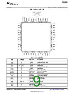
PIN ASSIGNMENTS (continued)
NAME
DVDD
GPIO1
GPIO2
GPIO3
GPIO4
IN1N(1)
IN1P
TERMINAL
FUNCTION
Supply
DESCRIPTION
48, 50
42
44
45
46
15
16
13
14
11
12
9
Digital power supply
Digital input/output
Digital input/output
Digital input/output
Digital input/output
Analog input
Analog input
Analog input
Analog input
Analog input
Analog input
Analog input
Analog input
Analog input
Analog input
Analog input
Analog input
Analog input
Analog input
Analog input
Analog input
—
General-purpose input/output pin
General-purpose input/output pin
GPIO3 in normal mode
GPIO4 in normal mode
Differential analog negative input 1
Differential analog positive input 1
Differential analog negative input 2
Differential analog positive input 2
Differential analog negative input 3
Differential analog positive input 3
Differential analog negative input 4
Differential analog positive input 4
Differential analog negative input 5
Differential analog positive input 5
Differential analog negative input 6
Differential analog positive input 6
Differential analog negative input 7
Differential analog positive input 7
Differential analog negative input 8
Differential analog positive input 8
No connection
IN2N
IN2P
IN3N
IN3P
IN4N
IN4P
10
7
IN5N
IN5P
8
IN6N
5
IN6P
6
IN7N
3
IN7P
4
IN8N
1
IN8P
2
NC
27, 29
64
36
31
40
17
18
38
35
28
30
55
26
25
24
Reserved
RESET
RESV1
SCLK
SRB1
SRB2
START
PWDN
VCAP1
VCAP2
VCAP3
VCAP4
VREFN
VREFP
Analog output
Digital input
Digital input
Digital input
Analog input/output
Analog input/output
Digital input
Digital input
—
Leave as open circuit
System reset; active low
Reserved for future use. Must tie to logic low (DGND)
SPI clock
Patient stimulus, reference, and bias signal 1
Patient stimulus, reference, and bias signal 2
Start conversion
Power-down; active low
Analog bypass capacitor
—
Analog bypass capacitor
Analog
Analog bypass capacitor
Analog output
Analog input
Analog input/output
Analog bypass capacitor
Negative reference voltage
Positive reference voltage
(1) Connect unused analog inputs IN1x to IN8x to AVDD.
10
Submit Documentation Feedback
Copyright © 2012, Texas Instruments Incorporated
Product Folder Link(s): ADS1299

 TI [ TEXAS INSTRUMENTS ]