U211B2/ B3
95 10716
V
Mains
Supply
/2
3/2
2
V
GT
Trigger
Pulse
t
p
t
pp
= 4.5 t
p
V
L
Load
Voltage
I
L
Load
Current
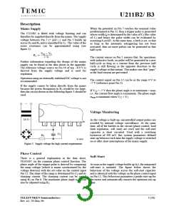
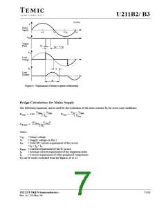
Figure 6. Explanation of terms in phase relationship
Design Calculations for Mains Supply
The following equations can be used for the evaluation of the series resistor R for worst case conditions:
1
VMmin – VSmax
2 Itot
VM – VSmin
2 ISmax
R1max
0.85
R1min
2
(VMmax – VSmin
)
P(R1max)
where:
2 R1
V
M
= Mains voltage
VS
= Supply voltage on Pin 3
= Total DC current requirement of the circuit
= I + I + I
I
tot
S
p
x
I
I
I
= Current requirement of the IC in mA
= Average current requirement of the triggering pulse
= Current requirement of other peripheral components
Smax
p
x
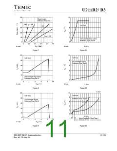
R can be easily evaluated from the figures 20 to 22.
1
TELEFUNKEN Semiconductors
7 (20)
Rev. A1, 29-May-96

 TEMIC [ TEMIC SEMICONDUCTORS ]