U211B2/ B3
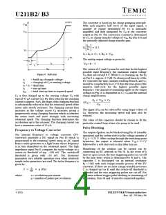
(reference voltage Pin 16) then a latch is set and the load
limiting is turned on. A current source (sink) controlled
by the control voltage on Pin 15 now draws current from
Pin 12 and lowers the control voltage on Pin 12 so that the
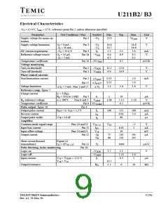
C = 1 F
10 V
phase angle is increased to
.
max
18
17
16
15
The simultaneous reduction of the phase angle during
which current flows causes firstly: a reduction of the
rotational speed of the motor which can even drop to zero
if the angular momentum of the motor is excessively
R = 1 M
large, and secondly: a reduction of the potential on C
9
which in turn reduces the influence of the current sink on
Pin 12. The control voltage can then increase again and
bring down the phase angle. This cycle of action sets up
a “balanced condition” between the “current integral” on
Pin 15 and the control voltage on Pin 12.
1
2
3
4
95 10363
Figure 5. Operation delay
Apart from the amplitude of the load current and the time
during which current flows, the potential on Pin 12 and
hence the rotational speed also affects the function of the
load limiting. A current proportional to the potential on
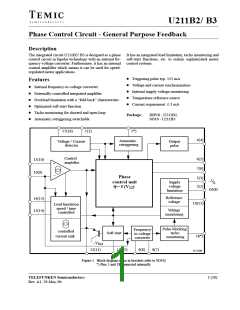
Control Amplifier (Figure 2)
The integrated control amplifier with differential input
compares the set value (Pin 11) with the instantaneous
value on Pin 10 and generates a regulating voltage on the
output Pin 12 (together with the external circuitry on
Pin 12) which always tries to hold the actual voltage at the
value of the set voltages. The amplifier has a
transmittance of typically 1000 A/V and a bipolar
current source output on Pin 12 which operates with
typically ±110 A. The amplification and frequency
Pin 10 gives rise to a voltage drop across R , via Pin 14,
10
so that the current measured on Pin 14 is smaller than the
actual current through R .
8
This means that higher rotational speeds and higher
current amplitudes lead to the same current integral.
Therefore, at higher speeds, the power dissipation must
be greater than that at lower speeds before the internal
threshold voltage on Pin 15 is exceeded. The effect of
speed on the maximum power is determined by the
response are determined by R , C , C and R (can be left
7
7
8
11
out). For open loop operation, C , C , R , R , C , C and
4
5
6
7
7
8
resistor R and can therefore be adjusted to suit each
10
R
11
can be omitted. Pin 10 should be connected with
individual application.
Pin 12 and Pin 8 with Pin 2. The phase angle of the
triggering pulse can be adjusted using the voltage on
Pin 11. An internal limitation circuit prevents the voltage
If, after the load limiting has been turned on, the
momentum of the load sinks below the “o-momentum”
set using R , then V will be reduced. V can then in-
on Pin 12 from becoming more negative than V + 1 V.
16
10
15
12
crease again so that the phase angle is reduced. A smaller
phase angel corresponds to a larger momentum of the mo-
tor and hence the motor runs up - as long as this is allowed
by the load momentum. For an already rotating machine,
the effect of rotation on the measured “current integral”
ensures that the power dissipation is able to increase with
the rotational speed. the result is: a current controlled
accelleration run-up., which ends in a small peak of accel-
leraton when the set point is reached. The latch of the load
limiting is simultaneously reset. The speed of the motor
is then again under control and it is capable of carrying its
full load. The above mentioned peak of accelleration
depends upon the ripple of actual speed voltage. A large
amount of ripple also leads to a large peak of
accelleration.
Load Limitation
The load limitation, with standard circuitry, provides
absolute protection against overloading of the motor. the
function of the load limiting takes account of the fact that
motors operating at higher speeds can safely withstand
large power dissipations than at lower speeds due to the
increased action of the cooling fan. Similary, consider-
ations have been made for short term overloads for the
motor which are, in practice, often required. These
finctions are not damaging and can be tolerated.
In each positive half-cycle, the circuit measures via R
the load current on Pin 14 as a potential drop across R
and produces a current proportional to the voltage on
Pin 14. This current is available on Pin 15 and is
10
8
integrated by C . If, following high current amplitudes or The measuring resistor R should have a value which
9
8
a large phase angle for current flow, the voltage on C
ensures that the amplitude of the voltage across it does not
9
exceeds an internally set threshold of approx. 7.3 V exceed 600 mV.
TELEFUNKEN Semiconductors
5 (20)
Rev. A1, 29-May-96

 TEMIC [ TEMIC SEMICONDUCTORS ]