U211B2/ B3
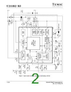
Design Hints
Practical trials are normally needed for the exact following table shows the effect of the circuitry on the
determination of the values of the relevant components in important parameters of the load limiting and summarises
the load limiting. To make this evaluation easier, the the general tendencies.
Parameters
Component affected
R
10
R
9
C
9
P
P
P
increases
increases
increases
n.e.
decreases
decreases
n.e.
n.e.
max
n.e.
min
/
n.e.
max min
t
t
decreases
increases
increases
increases
d
n.e.
r
P
P
– maximum continuous power dissipation
– power dissipation with no rotation
– operation delay time
P = f n
(n)
0
max
min
1
P = f n = 0
1
(n)
t
t
d
– recovery time
r
n.e
– no effect
Pulse Output Stage
General Hints and Explanation of Terms
To ensure safe and trouble-free operation, the following
points should be taken into consideration when circuits
are being constructed or in the design of printed circuit
boards.
The pulse output stage is short circuit protected and can
typically deliver currents of 125 mA. For the design of
smaller triggering currents, the function I = f(R ) has
GT
GT
been given in the data sheets in the appendix.
–
–
The connecting lines from C to Pin 7 and Pin 2
should be as short as possible: The connection to Pin 2
should not carry any additional high current such as
2
Automatic Retriggering
The variable automatic retriggering prevents half cycles
without current flow, even if the triac is turned off earlier
e.g. due to a collector which is not exactly centered (brush
lifter) or in the event of unsuccessful triggering. If it is
necessary, another triggering pulse is generated after a
time lapse which is determined by the repetition rate set
the load current. When selecting C ,
a low
2
temperature coefficient is desirable.
The common (earth) connections of the set-point
generator, the tacho-generator and the final
interference suppression capacitor C of the f/V
4
by resistance between Pin 5 and Pin 3 (R ). With the
converter should not carry load current.
5-3
maximum repetition rate (Pin 5 directly connected to
Pin 3), the next attempt to trigger comes after a pause of
–
–
The tacho-generator should be mounted without
influence by strong stray fields from the motor.
4.5 t and this is repeated until either the triac fires or the
p
The connections from R and C should be as short
10
5
half-cycle finishes. If Pin 5 is connected, then only one
trigger pulse per half-cycle is generated. Because the
as possible.
To achieve a high noise immunity, a maximum ramp
voltage of 6 V should be used.
value of R determines the charging current of C , any
5-3
2
repetition rate set using R is only valid for a fixed value
5-3
of C .
The typical resistance R can be calculated from I as
follows:
2
T(ms)
1.13(V)
6(V)
103
R (k )
C nF)
T = Period duration for mains frequency
(10 ms at 50 Hz)
C = Ramp capacitor, max. ramp voltage 6 V
and constant voltage drop at R = 1.13 V.
A 10% lower value of R (under worst case conditions)
is recommended.
6 (20)
TELEFUNKEN Semiconductors
Rev. A1, 29-May-96

 TEMIC [ TEMIC SEMICONDUCTORS ]