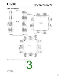
TSC80C31/80C51
When the port latch contains a 0, all pFETS in Figure 4.
When an I/O pin son Ports 1, 2, or 3 is used as an input,
are off while the nFET is turned on. When the port latch the user should be aware that the external circuit must
makes a 0-to-1 transition, the nFET turns off. The strong sink current during the logical 1-to-0 transition. The
pFET, T1, turns on for two oscillator periods, pulling the maximum sink current is specified as ITL under the D.C.
output high very rapidly. As the output line is drawn high, Specifications. When the input goes below
pFET T3 turns on through the inverter to supply the IOH approximately 2 V, T3 turns off to save ICC current. Note,
source current. This inverter and T form a latch which when returning to a logical 1, T2 is the only internal
holds the 1 and is supported by T2.
pullup that is on. This will result in a slow rise time if the
user’s circuit does not force the input line high.
When Port 2 is used as an address port, for access to
external program of data memory, any address bit that
contains a 1 will have his strong pullup turned on for the
entire duration of the external memory access.
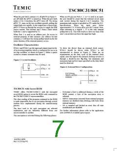
Oscillator Characteristics
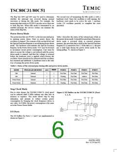
XTAL1 and XTAL2 are the input and output respectively, To drive the device from an external clock source,
of an inverting amplifier which is configured for use as an XTAL1 should be driven while XTAL2 is left
on-chip oscillator, as shown in Figure 5. Either a quartz unconnected as shown in Figure 6. There are no
crystal or ceramic resonator may be used.
requirements on the duty cycle of the external clock
signal, since the input to the internal clocking circuitry is
through a divide-by-two flip-flop, but minimum and
maximum high and low times specified on the Data Sheet
must be observed.
Figure 5. Crystal Oscillator.
Figure 6. External Drive Configuration.
TSC80C51 with Secret ROM
TEMIC offers TSC80C31/80C51 with the encrypted
secret ROM option to secure the ROM code contained in
the TSC80C31/80C51 microcontrollers.
–
–
–
Everytime a byte is addressed during a verify of the
ROM content, a byte of the encryption array is
selected.
MOVC instructions executed from external program
memory are disabled when fetching code bytes from
internal memory.
The clear reading of the program contained in the ROM
is made impossible due to an encryption through several
random keys implemented during the manufacturing
process.
EA is sampled and latched on reset, thus all state
modification are disabled.
The keys used to do such encryption are selected
randomwise and are definitely different from one For further information please refer to the application
microcontroller to another.
note (ANM053) available upon request.
This encryption is activated during the following phases :
MATRA MHS
7
Rev. E (14 Jan.97)

 TEMIC [ TEMIC SEMICONDUCTORS ]