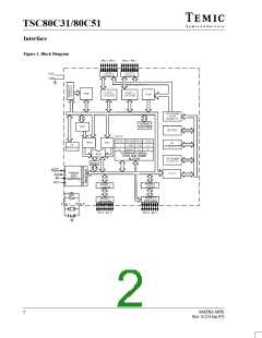
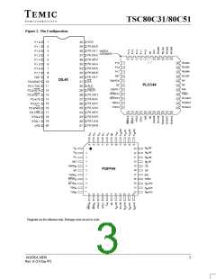
TSC80C31/80C51
The flag bits GF0 and GF1 may be used to determine The second way of terminating the Idle mode is with a
whether the interrupt was received during normal hardware reset. Since the oscillator is still running, the
execution or during the Idle mode. For example, the hardware reset needs to be active for only 2 machine
instruction that writes to PCON.0 can also set or clear one cycles (24 oscillator periods) to complete the reset
or both flag bits. When Idle mode is terminated by an operation.
enabled interrupt, the service routine can examine the
status of the flag bits.
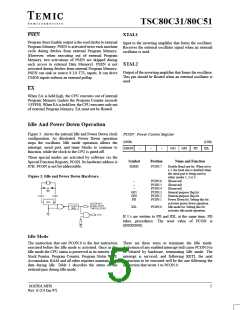
Power Down Mode
The instruction that sets PCON.1 is the last executed prior Table 1 describes the status of the external pins while in
to entering power down. Once in power down, the the power down mode. It should be noted that if the power
oscillator is stopped. The contents of the onchip RAM and down mode is activated while in external program
the Special Function Register is saved during power down memory, the port data that is held in the Special Function
mode. The hardware reset initiates the Special Fucntion Register P2 is restored to Port 2. If the data is a 1, the port
Register. In the Power Down mode, VCC may be lowered pin is held high during the power down mode by the
to mi-nimize circuit power consumption. Care must be strong pullup, T1, shown in Figure 4.
taken to ensure the voltage is not reduced until the power
down mode is entered, and that the voltage is restored
before the hardware reset is applied which freezes the
oscillator. Reset should not be released until the oscillator
has restarted and stabilized. A hardware reset is the only
way of exiting the power down mode.
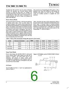
Table 1. Status of the external pins during idle and power down modes.
MODE
Idle
PROGRAM MEMORY
ALE
PSEN
PORT0
Port Data
Floating
Port Data
Floating
PORT1
Port Data
Port Data
Port Data
Port Data
PORT2
Port Data
Address
PORT3
Port Data
Port Data
Port Data
Port Data
Internal
External
Internal
External
1
1
0
0
1
1
0
0
Idle
Power Down
Power Down
Port Data
Port Data
Stop Clock Mode
Due to static design, the TSC80C31/80C51 clock speed
can be reduced until 0 MHz without any data loss in
memory or registers. This mode allows step by step
utilization, and permits to reduce system power
consumption by bringing the clock frequency down to
any value. At 0 MHz, the power consumption is the same
as in the Power Down Mode.
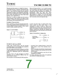
Figure 4. I/O Buffers in the TSC80C31/80C51 (Ports
1, 2, 3).
I/O Ports
The I/O buffers for Ports 1, 2 and 3 are implemented as
shown in Figure 4.
6
MATRA MHS
Rev. E (14 Jan.97)

 TEMIC [ TEMIC SEMICONDUCTORS ]